Magnetic tape driving apparatus comprising a tape separation portion that separates a magnetic tape from a magnetoresistive head unit

a technology of driving apparatus and magnetic tape, which is applied in the direction of speed-changing/reversing arrangements, recording on magnetic tapes, instruments, etc., can solve the problems of increasing friction between, damage to the magnetic head damage to the magnetic tape or the magnetic tape, so as to prevent damage to the magnetic head and the magnetic tape, and suppress the generation of foreign matter

Active Publication Date: 2012-04-17
FUJIFILM CORP
View PDF19 Cites 6 Cited by
  • Summary
  • Abstract
  • Description
  • Claims
  • Application Information

AI Technical Summary

Benefits of technology

[0009]It is an object of the present invention to provide a magnetic tape driving apparatus that does not suffer from damage to a magnetic head and a magnetic tape when the magnetic tape makes a transition from the stopped state to the running state and vice versa or changes in the running direction, and that can suppress the generation of foreign matter (contamination) and thus can prevent damage such as flaws to the magnetic tape and the magnetic head.
[0012]The present invention can prevent damage to the magnetic head and the magnetic tape when the magnetic tape starts or stops running. Moreover, the present invention can suppress the generation of foreign matter (contamination) and thus can prevent damage such as flaws to the magnetic tape and the magnetic head.

Problems solved by technology

When the surface of the magnetic tape is smoothed, the contact area between the magnetic tape and a magnetic head is increased, thus increasing friction between them.
If this static friction is increased, the magnetic tape and the magnetic head can be damaged, or the surface of the magnetic tape can be scraped off by the magnetic head to generate foreign matter (contamination).
Therefore, when the start and stop motions of the magnetic tape are repeated with the magnetic head being in contact with the portion an which no recess is formed) between the BOT and EOT portions, the magnetic head or the magnetic tape are damaged by the static friction between them.
Thus, the magnetic tape can be damaged or even cut.
The static friction also can damage the MR element or the like of the magnetic head.
Moreover, the same problem arises when the magnetic tape makes a transition from the running state to the stopped state.
Further, the same problem also arises when the running direction of the magnetic tape is changed from the first (e.g., forward) direction to the second (e.g., reverse) direction and vice versa.

Method used


Image

  • Magnetic tape driving apparatus comprising a tape separation portion that separates a magnetic tape from a magnetoresistive head unit
  • Magnetic tape driving apparatus comprising a tape separation portion that separates a magnetic tape from a magnetoresistive head unit
  • Magnetic tape driving apparatus comprising a tape separation portion that separates a magnetic tape from a magnetoresistive head unit

Examples


embodiment 1

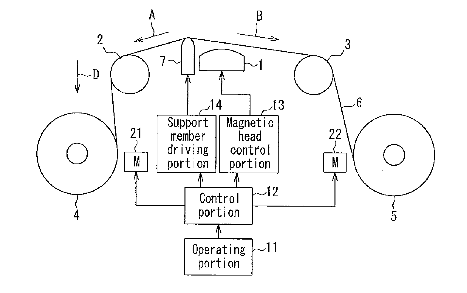
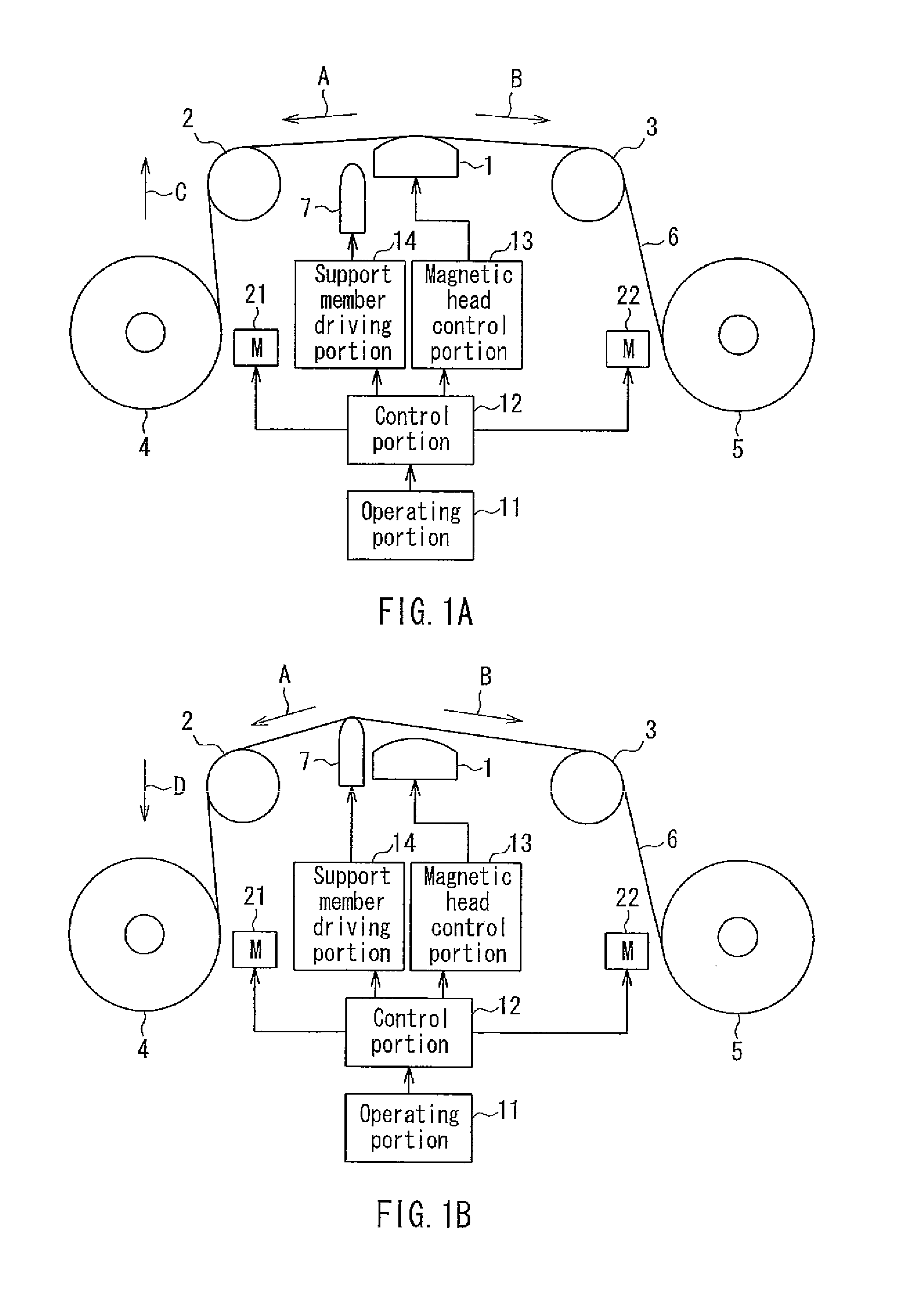
[0033]FIGS. 1A and 1B show the configuration of a magnetic tape driving apparatus of Embodiment 1. A support member 7 is located at a first position in FIG. 1A and at a second position in FIG. 1B.

[0034]A magnetic head 1 includes, e.g., an MR (magneto-resistance effect) element and is capable of recording and reproducing various information with respect to a magnetic tape 6. Tape guide members 2, 3 are placed on the input and output sides of the magnetic head 1, and serve to control the winding angle of the magnetic tape 6 or the position of the magnetic tape 6 in the width direction. A first reel 4 is placed in the magnetic tape driving apparatus beforehand, and is rotated by a motor 21. A second reel 5 is placed in a removable cartridge not shown), and when the cartridge is inserted into the magnetic tape driving apparatus, the second reel 5 is put on a reel table (not shown) of the apparatus. The reel table is rotated by a motor 22 that is driven by a control portion 12. The magne...

embodiment 2

[0064]FIGS. 3A and 3B show the configuration of a magnetic tape driving apparatus of Embodiment 2. This configuration differs from Embodiment 1 shown in FIGS. 1A and 1B in that an air injection member 8 is used instead of the support member 7, and an air control portion 15 is used instead of the support member driving portion 14. The air injection member 8 is located in the vicinity of the magnetic head 1 with its nozzle, through which a stream of air E issues, facing the magnetic tape 6. The air control portion 15 outputs air injection and air stop instructions to the air injection member 8 after the receipt of these instructions from the control portion 12.

[0065]The air injection member 8 and the air control portion 15 are described as an example of a tape separation portion.

[0066]Although the operations of the magnetic tape driving apparatus of this embodiment are substantially similar to those shown in FIGS. 2A and 2B, the movement control of the support member 7 in the steps S1...

embodiment 3

[0073]FIGS. 4A and 4B show the configuration of a magnetic tape driving apparatus of Embodiment 3. This configuration differs from Embodiment 1 shown in FIGS. 1A and 1B in that a rotatable roller 9 is used instead of the support member 7, and a roller driving portion 16 is used instead of the support member driving portion 14.

[0074]The rotatable roller 9 is located in the vicinity of the magnetic head 1 so as to be movable between the first position and the second position (as with Embodiment 1). The rotatable roller 9 is configured to rotate in accordance with the running of the magnetic tape 6 when it comes into contact with the magnetic tape 6. The rotatable roller 9 has, e.g., a cylindrical shape as shown in FIG. 5A, and may be made of AlTiC (Al2O3—TiC). Moreover, it is desirable to reduce the radius of curvature of a portion in contact with the magnetic tape 6 so that the contact area between the rotatable roller 9 and the magnetic tape 6 becomes smaller. The preferred radius o...


PUM

PropertyMeasurementUnit
surface smoothness Raaaaaaaaaaa
frictionaaaaaaaaaa
static frictionaaaaaaaaaa

Abstract

A magnetic tape driving apparatus of the present invention includes a support member for separating a magnetic tape from a magnetic head on at least one of a tape input side and a tape output side of the magnetic head. The support member separates the magnetic tape from the magnetic head at least when a tape driving portion causes the magnetic tape to start running and / or to stop running. With this configuration, the magnetic tape driving apparatus does not suffer from damage to the magnetic head and the magnetic tape when the magnetic tape makes a transition from the stopped state to the running state and vice versa or changes in the running direction.

Description

BACKGROUND OF THE INVENTION[0001]1. Field of the Invention[0002]The present invention relates to a magnetic tape driving apparatus that can drive a magnetic tape. In particular, the present invention is useful for a magnetic tape apparatus that uses a magnetic sensor head to linearly record data on a magnetic tape with a surface smoothness Ra of 3.0 nm or less.[0003]2. Description of Related Art[0004]A magnetic tape is a kind of magnetic recording medium and for various applications such as an audio tape, a video tape, and a computer tape. Particularly, in the field of backup tapes for computers, tapes with a storage capacity of hundreds of gigabytes per volume have been commercialized along with an increase in capacity of a hard disk to be backed up. In the future, backup tapes with a larger capacity are essential to deal with a further increase in capacity of the hard disk.[0005]For a magnetic tape used as a backup tape, the recording wavelength becomes shorter as the recording ca...

Claims


Application Information

Patent Timeline
Patent Type & Authority Patents(United States)
IPC IPC(8): G11B5/008
CPCG11B5/54G11B15/12G11B15/44G11B15/62
Inventor FUJITA, MASAOKUSE, SADAMU
Owner FUJIFILM CORP
Why Eureka
Try Eureka