Multipurpose flow module

a flow module and multi-purpose technology, applied in the direction of liquid-gas reaction process, pipe heating/cooling, chemical/physical processes, etc., can solve the problems of more turbulence in the fluid flow, manufacturing limitations, and difficulty in creating the desired pressure condition, so as to prevent leakage and improve the effect of chemical resistance and good chemical resistan

Inactive Publication Date: 2012-04-24
ALFA LAVAL CORP AB
View PDF14 Cites 8 Cited by
  • Summary
  • Abstract
  • Description
  • Claims
  • Application Information

AI Technical Summary

Benefits of technology

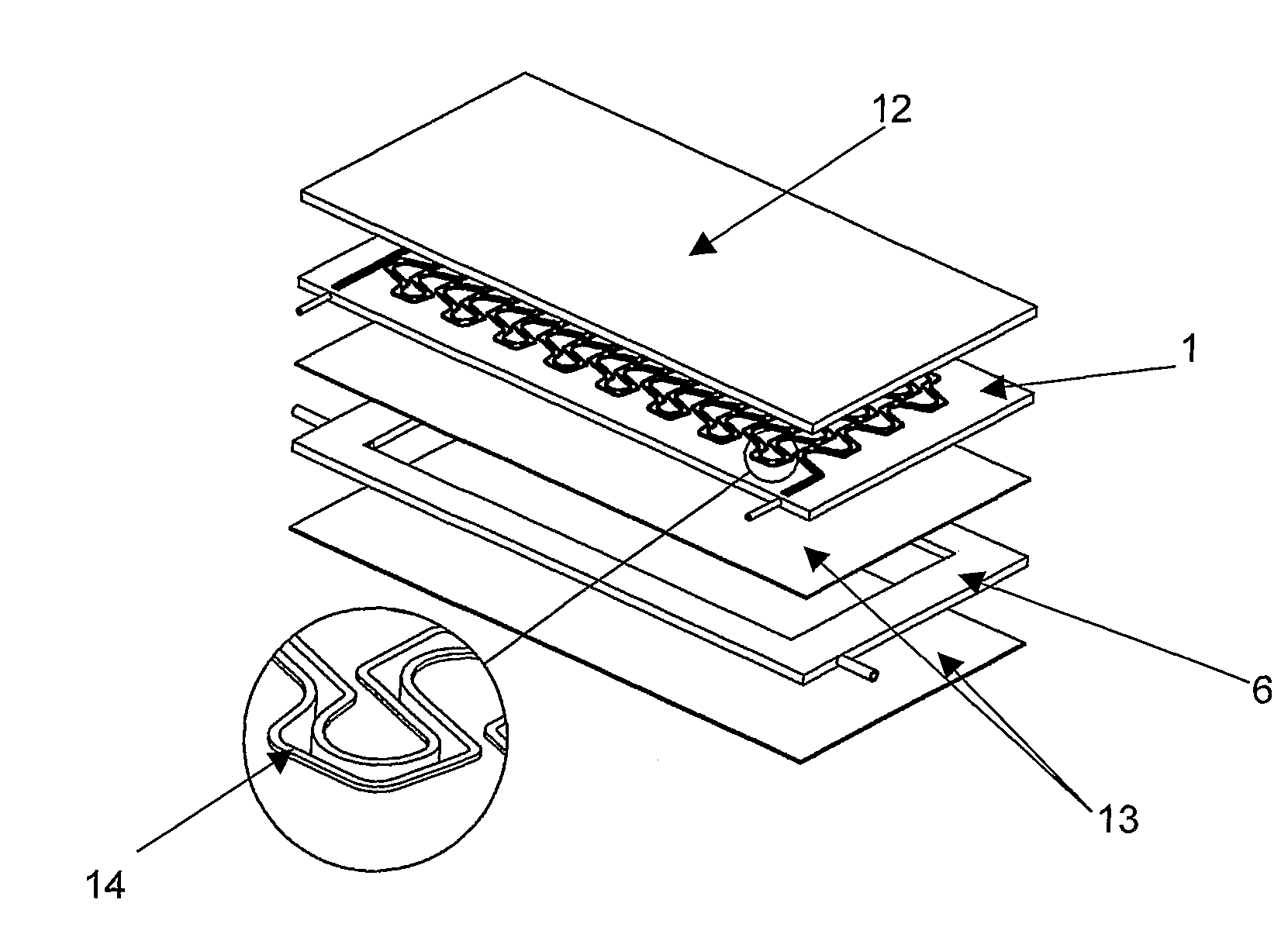
[0022]According to another alternative embodiment of the invention protruded zones along the circumferences of the flow channel may be arranged, on each side next to the flow channel, to enable a gasket to close the flow plate against an end plate or against a barrier plate, or a heat exchanger plate to prevent leakage.
[0023]A gasket may close or seal the flow plate from leaking, and the gasket can be arranged to cover or close the flow channel against an end plate, against a barrier plate, an insulator or against a heat exchanger plate.
[0025]The gasket may be a flat sheet, or multi layer sheet of a suitable material, example of such material may be multi layer expanded polytetrafluoroethylene (ePTFE), polytetrafluoroethylene (PTFE), perfluorelastomers, or fluorelastomers, polyetheretherketone (PEEK), polypropene (PP), etc. The material of the gasket may be a soft material such as soft PEEK, PP, PTFE etc. or Viton®, Teflon®, Kalrez® etc. or the gasket could be metallic O-rings or sealing elements of a suitable metallic material. The material of the gasket should have good chemical resistance depending on the process, but if the process does not need good chemical resistance then other materials are sufficient. The gasket material may be soft, until the clamping forces close the structure, and the material may be deformable with very small lateral dilatation. Thus, the gasket may fill out any imperfections in the sealing surfaces. According to one alternative embodiment the gasket may be shaped to correspond to the flow channels, formed by for example a printing tool, or the gasket may be compressed by external force to the desired shape to minimise gasket bulge down in the flow channel, resulting in that the cross section remains the same, and absorption of fluid in the gasket is reduced.
[0032]Each channel, depression, channel, groove or cut through area may have fins, wings, structured package material, metallic foams, etc. to increase heat transfer area, and to enhance turbulence of the heat exchanger fluid to improve the heat transfer according to one alternative embodiment of the invention.
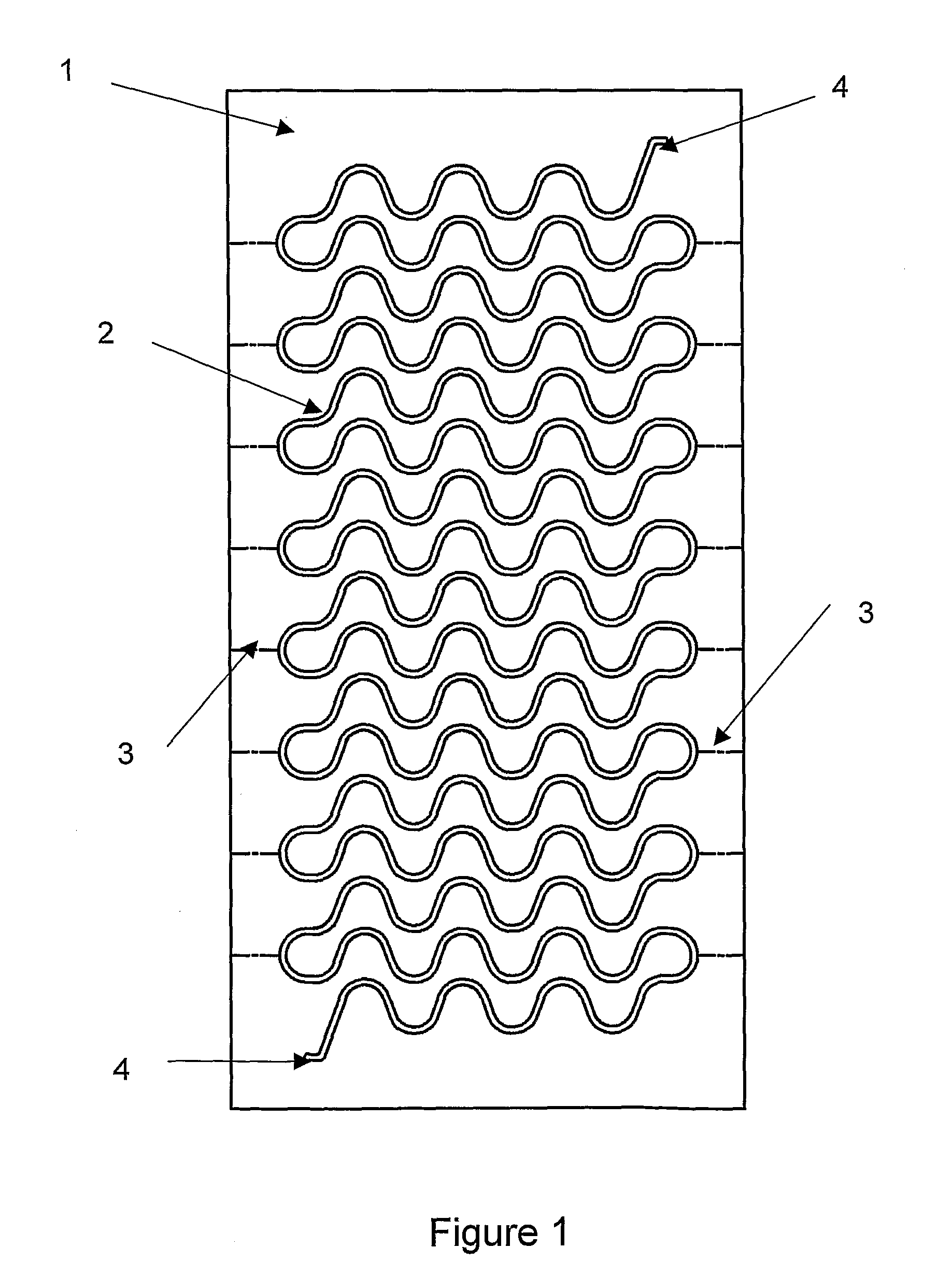
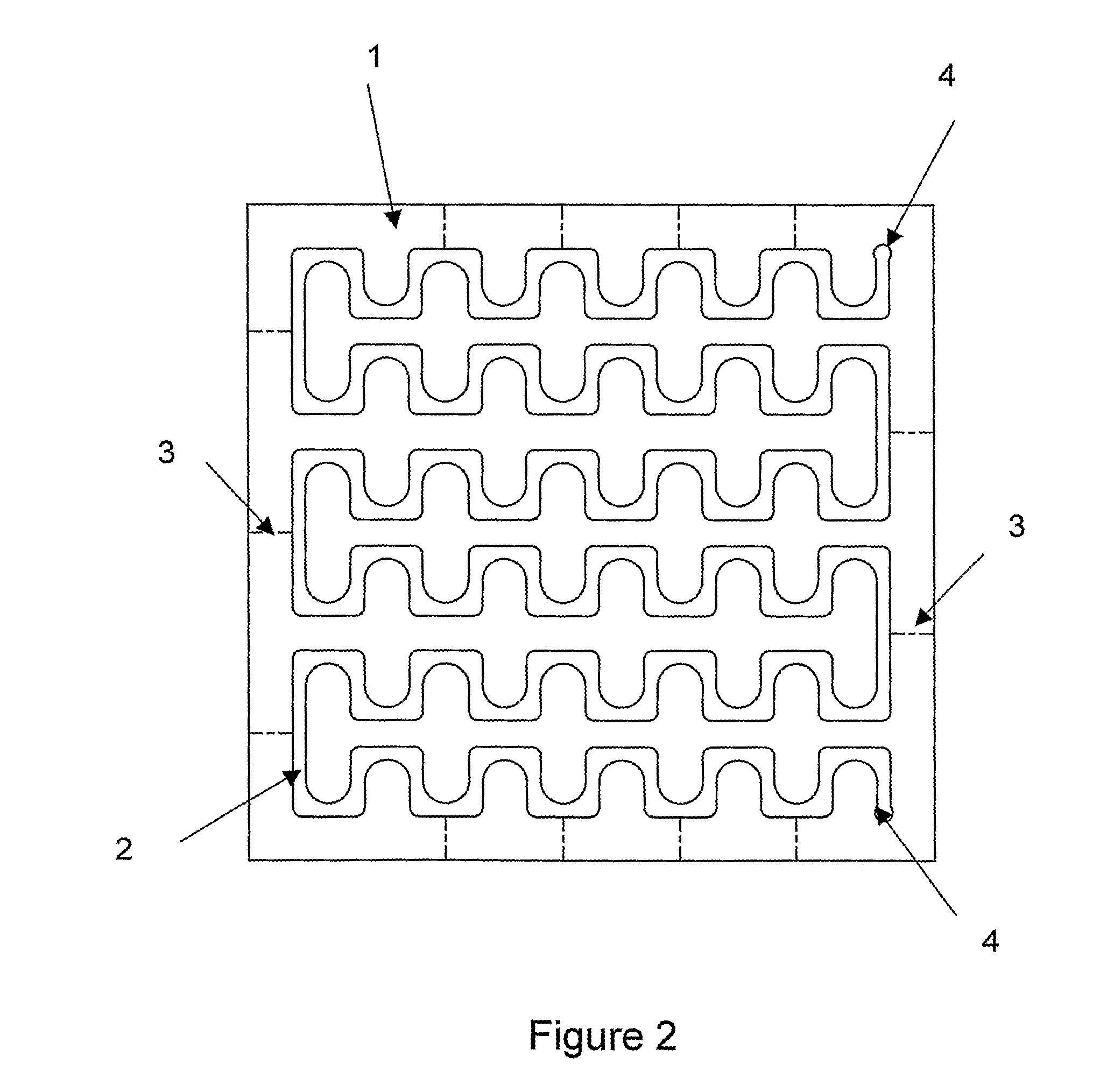
[0052]The performance of the multipurpose flow module will herein after be described in principal. The design of the flow channels is suitably made for flexibility in the purpose of the desired process. It is favourable for many processes that mixing of miscible fluids at a desired flow rate will result in uniform and small micro-mixing timescale corresponding to a desired pressure drop per plate. Therefore, the flow channel of each flow plate or flow section is having a compact design and the length of each channel is designed for the purpose of the flow module. The flow channel has one or more mixing zones in the form bends or curved zones. The mixing zones may be in the form of corners at the bends or the curved zones of the flow channel according to one alternative of the invention. The mixing zones could be micro mixing zones. The design of the multipurpose flow module offers good heat transfer, which favours tempering of chemical reactions, mixing of fluids, extractions, etc. High heat transfer comes from a combination of traditional convective heat transfer into the utility fluid and conductive heat transfer through the heat conducting material of the multipurpose flow module. The combination of good mixing and redistribution of fluid within the flow channel and the high heat transfer rates will provide excellent thermal control of the flow medium.

Problems solved by technology

If the length of the hole (T) is large then it will be very difficult to create the desired pressure condition at that point.
For small size nozzles length (T) and diameter (D) will be very small and manufacturing limitations will occur.
The more intensive design of the flow channel the more turbulence in the fluid flow.

Method used


Image

  • Multipurpose flow module
  • Multipurpose flow module
  • Multipurpose flow module

Examples


example 1

[0100]In Example 1 a multipurpose flow module was tested, which module operates at process flow rates of 1.5-10 l / hr (0.1-0.7 m / s). The flow rate in this example was 5 l / hr. The micro-mixing timescale in a water-like fluid, as determined by reactive mixing experiment, was 30 milliseconds. This corresponds to a pressure drop of 0.5 Bar per flow plate. The utility fluid was water having a temperature at about 10° C. and a flow rate of 40 l / hr was cooling a hotter process fluid, which had a flow rate of 5 l / hr—in the initial part of the module are cooling rates of more than 30° C. / s achieved for this pseudo co-current configuration.

[0101]The combination of good mixing and redistribution of fluid within the channel and the high heat transfer rates were combined to provide excellent thermal control of the reaction medium. The pressure was up to 20 bar—referring to a stainless steel reactor with GORE® ePTFE gasket and HPLC fittings.

[0102]The design of the multipurpose flow module also off...

example 2

[0103]A multipurpose flow module was tested in this example, the dimensions of the flow channel of the module were: cross-section 1.5 mm×2 mm in average, process hydraulic diameter 2.16 mm, length of the flow channel 3.113 m. The flow rates were within the range of 1-10 l / hr during the tests.

[0104]The shape of the residence time distributions were similar at all flow rates tested, which can be seen in FIG. 22, indicating common hydrodynamics across these conditions. FIG. 22 shows a smooth peak, with sharper rise and longer decrease. The width of the distribution decreases as the flow rate is increased. There are neither short cuts nor stagnant regions, thus a plug flow was created in the tested flow channel.

example 3

[0105]In Example 3 a disperser nozzle was tested in a multipurpose flow module. The nozzle flow was measured in continuous operating mode, for different sized nozzles, for a range of feed pump operating pressures.

[0106]The flow ranges are summarised in the graph of FIG. 23. The graph shows flow rates for different nozzle sizes with a fully open valve. By using an operating valve, i.e. pulsed mode, the flow rate could be lowered down to less than 1% of these flows for each nozzle size.


PUM


Abstract

The present invention relates to a multipurpose flow module comprising flow plates and / or heat exchanger plates stacked together, which flow plate having a flow channel and one or more connection ports. To each flow plate or heat exchanger plate one or more barrier plates may be attached. The present invention further relates to a method for extraction, for reaction, for mixing, or combinations thereof in the multipurpose flow module, and to uses of the multipurpose flow module.

Description

FIELD OF THE INVENTION[0001]The present invention relates to a multipurpose flow module, a method for extraction, for reaction, for separation, for mixing, or combinations thereof in a multipurpose flow module, and use of the multipurpose flow module.BACKGROUND OF INVENTION[0002]Examples of continuous chemical reactors, which have a continuous flow of materials or reactants into the reactor and a continuous flow of materials or products out of the reactor, are disclosed by WO 2004 / 089533, WO 03 / 082460, EP 1123735, and EP 0701474 B1. There are different features, which are important for flow modules, such as flexibility in set-up, flow configuration, mixing properties, temperature control, monitoring, residence times etc.[0003]Therefore, a number of problems to overcome when designing and building multipurpose flow modules are for example, but are not limited to, leakage, enabling of visual inspection, cleaning of flow paths, adaptation of process flow path to get desired residence t...

Claims


Application Information

Patent Timeline
Patent Type & Authority Patents(United States)
IPC IPC(8): F16K49/00B01J10/00B01J19/00B01F25/313B01F25/433B01F33/30
CPCB01F5/0451B01F5/0646B01F5/0647B01F5/0648B01F13/0059B01J19/0093B01J19/249F28D9/0081F28F3/02F28F3/083F28F3/12F28F9/26B01J2219/00783B01J2219/0081B01J2219/00835B01J2219/00873B01J2219/00907B01J2219/0097B01J2219/00975B01J2219/00977B01J2219/00986B01J2219/00995B01J2219/2453B01J2219/2458B01J2219/2462B01J2219/2474B01J2219/2496B01L3/5027Y10T137/6416F28F2250/102B01F25/3131B01F25/4332B01F25/4331B01F25/433B01F33/30
Inventor HOGLUND, KASPERNOREN, TOMMYJOHNSON, BARRYCARDELIUS, ERIK
Owner ALFA LAVAL CORP AB
Why Eureka
Try Eureka