
Raised axle and suspension system

a technology of suspension system and raised axle, which is applied in the directions of transportation and packaging, loading/unloading vehicle arrangment, transportation items, etc., can solve the problems of high cost of wheel chair lifts, extreme difficulty in delivering people, and handicapped individuals entering vehicles, etc., to achieve lower overall height, lower center of gravity, and taller entry height

Active Publication Date: 2012-04-24
PRESS RICHARD U
View PDF14 Cites 9 Cited by
  • Summary
  • Abstract
  • Description
  • Claims
  • Application Information

AI Technical Summary

Benefits of technology

[0015]The principal advantage of the Raised Axle and Suspension System is the capability of lowering the floor height of a wide variety of vehicles.

Problems solved by technology

This is extremely difficult for delivery people who have to re-enter the vehicle a great number of times a day.
Additional problems occur with handicapped individuals entering vehicles either by themselves, with help or in wheelchairs.
Wheel chair lifts are very expensive to be incorporated into a vehicle where they are required to lift the handicapped individual up to the floor height of the vehicle.
Most public vehicles are required to have wheelchair lifts for the handicapped which are expensive and take up a lot of space.
On commercial vehicles it takes a lot more time assisting a handicapped person into and out of the vehicle than the other passengers which can greatly affect the scheduled time of these operations.
This patent design still has the floor of the vehicle above the axle and could not be used for transporting handicapped people, and does not facilitate a walk-about interior.
None of these previous efforts, however, provides the benefits attendant with the Raised Axle and Suspension System.

Method used


Image

  • Raised axle and suspension system
  • Raised axle and suspension system
  • Raised axle and suspension system

Examples


Embodiment Construction

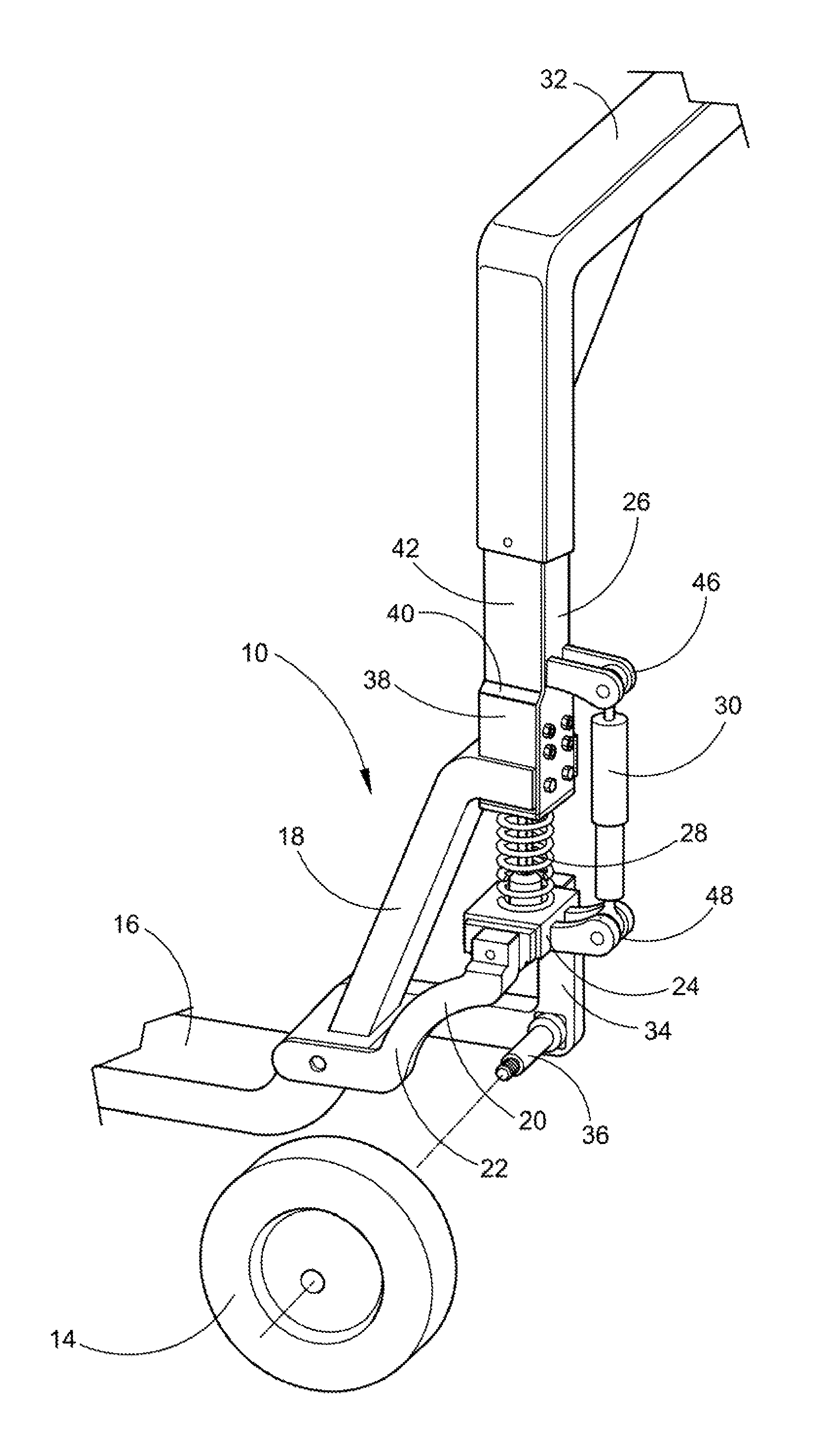
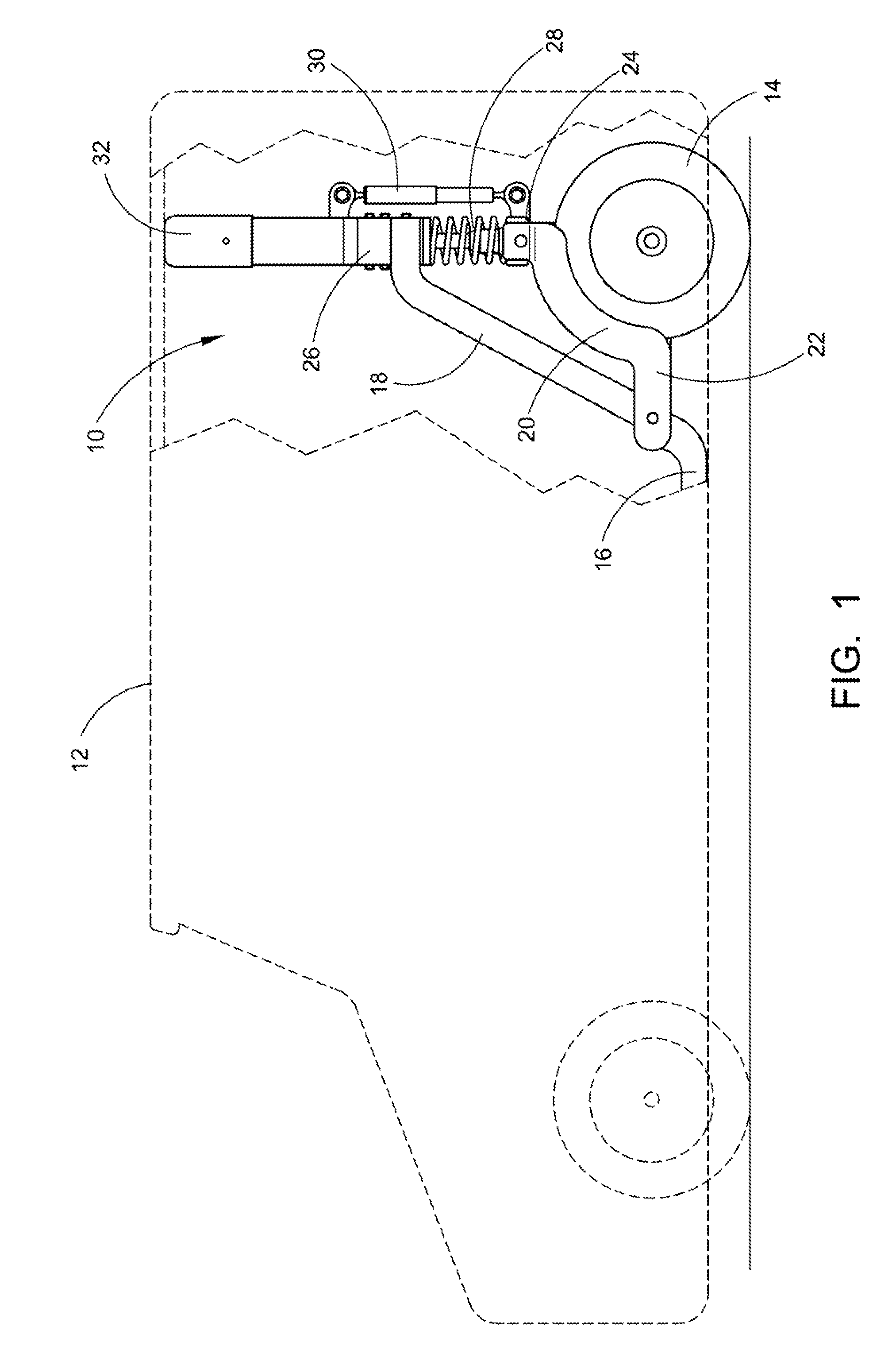
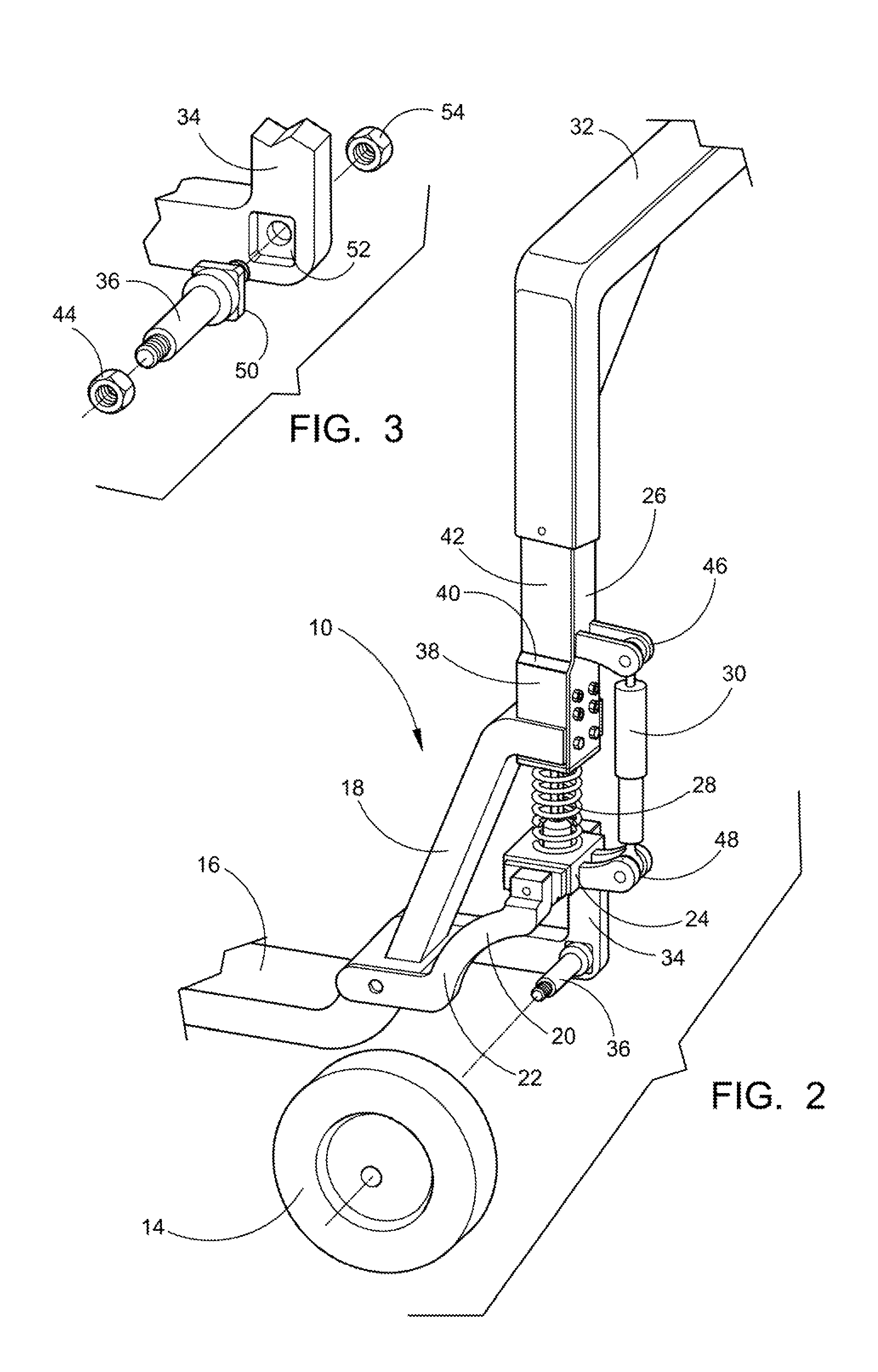
[0043]Referring now to the drawings, wherein similar parts of the preferred embodiment of the Raised Axle and Suspension System 10 are identified by like reference numerals, there is seen in FIG. 1 a side view of a conventional front wheel drive vehicle 12 incorporating the Raised Axle and Suspension System 10. The right side of the preferred Raised Axle and Suspension System 10 is a mirror image of the left side. This view illustrates the vehicles left side wheel 14, the frame attachment member 16 that is welded to the angular support member 18. The wheel side support member 20 of the wheel support casting 22 that is pivotally connected to the suspension base member 24 and the suspension support member 26 that is additionally welded to the angular support member 18. The suspension spring 28 extends between the suspension base member 24 and the suspension support member 26 along with a conventional shock absorber 30. The axle overarm 32 extends from the left side of the vehicle to t...


PUM


Abstract

The present invention is directed to a Raised Axle and Suspension System that consists of a unique design that is intended to be used on a wide variety of front wheel drive vehicles and trailers by raising the axle overarm to an overhead position. This is accomplished by having the wheels on stub axles attached to a pivoting wheel support castings that are attached to frame attachment members. Angular support members are fixably attached to the frame attachment members and suspension support members that connect to the axle overarm. The axle overarm extends from the left side of the vehicle to the right side. The suspension springs extend between the suspension base members that are pivotally connected to the wheel support castings and the suspension support members along with conventional shock absorbers creating a spring cushioning system.

Description

FIELD OF THE INVENTION[0001]This application is in the field of lowering the floor level for a wide variety of motor vehicles and trailers by raising the rear axle overarm to an overhead position and mounting the wheels on a suspension system using individual stub axles.BACKGROUND OF THE INVENTION[0002]This invention describes a new and unique design that raises the axle height of a wide range of vehicles including cars and minivans, delivery vans, handicapped vans, busses, campers and trailers to provide a curb level floor surface. The intended use of the overhead axle is for front wheel drive vehicles only or trailers. The axle consists of the rigid structure that connects two or more rear wheels of a motor vehicle or the two or more wheels of a trailer. The axle overarm is actually an extension of the vehicle frame and is connected to the unitized construction of the vehicle body.[0003]This is accomplished by having the rear axle structure above head height within these vehicles....

Claims


Application Information

Patent Timeline
Patent Type & Authority Patents(United States)
IPC IPC(8): B60G3/12B60G3/14
CPCB60G3/12B60G3/14B60G11/16B60G13/003B60G2204/124B60G2204/128
Inventor PRESS, RICHARD U.
Owner PRESS RICHARD U
Learn More