Machine for machining optical workpieces, in particular plastic spectacle lenses

a technology for optical workpieces and plastic spectacle lenses, which is applied in the field of plastic spectacle lenses, can solve the problems of unfavorable engraving, “dulling” of engraving images, etc., and achieve the effect of simple replacement and easy replacement of engraving tools

Active Publication Date: 2012-05-01
SATISLOH AG
View PDF32 Cites 8 Cited by
  • Summary
  • Abstract
  • Description
  • Claims
  • Application Information

AI Technical Summary

Benefits of technology

[0009]Starting from the prior art according to WO-A-97 / 13603, the object of the invention is to provide a machine for machining optical workpieces, in particular plastic spectacle lenses, comprising a fast tool arrangement, by means of which it is also possible to apply any desired, finely detailed markings to the workpiece without the workpiece having to be reclamped or unclamped for this purpose.
[0011]With the engraving tool arranged on the tool holder next to and parallel to the turning tool, in the working area one and the same machining machine can thus provide the workpiece with a permanent engraving immediately after the actual turning process using one and the same fast tool arrangement, without the workpiece having to be reclamped on a separate engraving machine for this purpose, which is conducive to a fast and accurate machining process. Since a tool that is different from the turning tool is used here, namely the engraving tool, of which the end facing towards the workpiece is essentially point-shaped, then unlike in the generic prior art the geometry of the marking that can be produced is not limited by the geometry of the turning tool. Very finely detailed engravings can be produced in particular by the needling engagement of the sharp engraving tool with the workpiece, i.e. by an engraving machining in which the engraving tool strikes the workpiece in rapid succession in the same way as a woodpecker strikes a tree. Furthermore, in the machine according to the invention, the engraving of the workpiece does not result in any wear on the turning tool, in the same way as the turning of the workpiece does not result in any wear on the engraving tool, which increases the life of the tools compared to the generic prior art. This is particularly important against the background that a blunt engraving tool might only push the material of the workpiece away during the engraving machining but the material then generally comes back, which may lead to undesirable “ageing” or “dulling” of the engraved image, especially in the case of the plastics material CR39.
[0015]The tool holder according to the invention comprises a base plate, which can be fixed to a pendulum part of a fast tool arrangement of the machine, and at least two mounts arranged on the base plate spaced apart from one another in a direction transverse to a movement direction of the pendulum part, one of which mounts serves to fix the turning tool while the other serves to fix a functional element selected from a group consisting of engraving tools, sensors and optionally further turning tools. This tool holder allows on the one hand, as already mentioned above, the engraving of the workpiece immediately after the actual turning process using one and the same fast tool arrangement, without the workpiece having to be reclamped on a separate engraving machine for this purpose. On the other hand, this tool holder may advantageously also carry further or other functional elements, depending on the respective machining requirements, such as a sensor for (in situ) geometry detection of the workpiece in the machine or a further turning tool so that, for example, pre-turning by means of a PCD or carbide turning tool held in one mount followed by finish-turning by means of a natural diamond turning tool held in the other mount can take place, without a tool change or clamping of the workpiece in another machine having to take place between these operations.
[0016]The flexibility of the tool holder according to the invention for a wide range of machining and measuring processes in the machine can furthermore be increased if the mounts are designed for releasably—as opposed to non-releasably—fixing the turning tool and the respective functional element.
[0017]If the tool holder according to the invention is to be used on a machine as described for example in the earlier German patent application DE 10 2005 021 638 A1 by the same Applicant, i.e. a machine in which the movement direction of the pendulum part of the fast tool arrangement and the workpiece rotation axis run parallel to one another, it is advantageous if at least the mount for the turning tool is attached to the base plate in a height-adjustable manner with respect to the plane in which the pendulum part can be moved, so that the height of the turning tool cutting edge can easily be adjusted with respect to the workpiece rotation axis.
[0022]Finally, it is preferred if the element which generates the retaining force comprises a magnet, in particular a permanent magnet, which allows easy replacement of the engraving tool or sensor with another engraving tool or sensor or simple swapping thereof.

Problems solved by technology

This is particularly important against the background that a blunt engraving tool might only push the material of the workpiece away during the engraving machining but the material then generally comes back, which may lead to undesirable “ageing” or “dulling” of the engraved image, especially in the case of the plastics material CR39.

Method used


Image

  • Machine for machining optical workpieces, in particular plastic spectacle lenses
  • Machine for machining optical workpieces, in particular plastic spectacle lenses
  • Machine for machining optical workpieces, in particular plastic spectacle lenses

Examples


Embodiment Construction

OF EMBODIMENTS

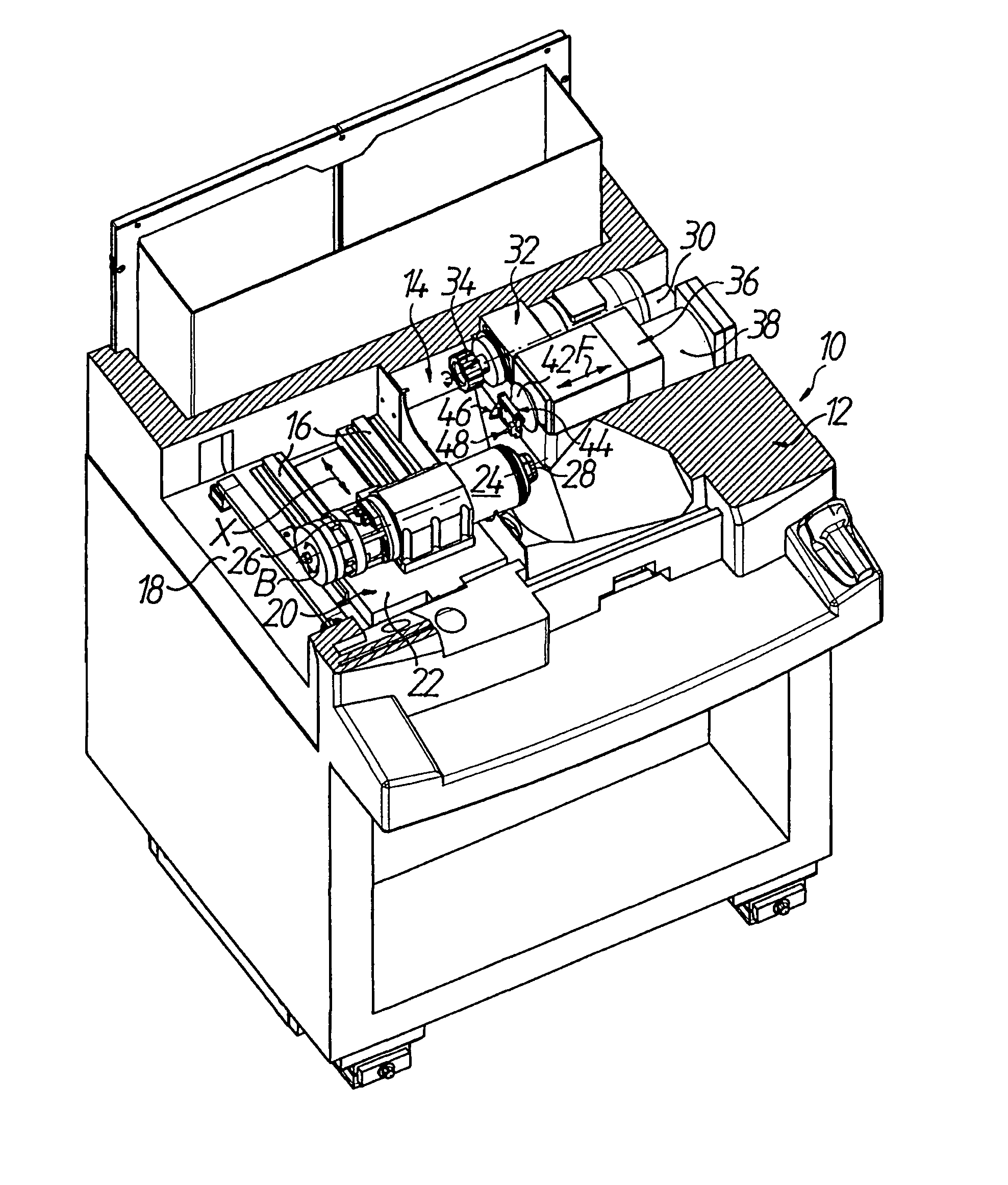
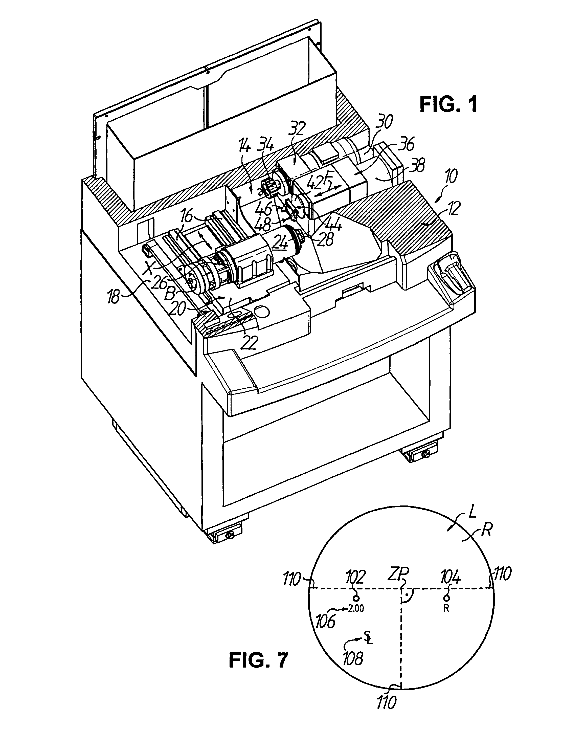
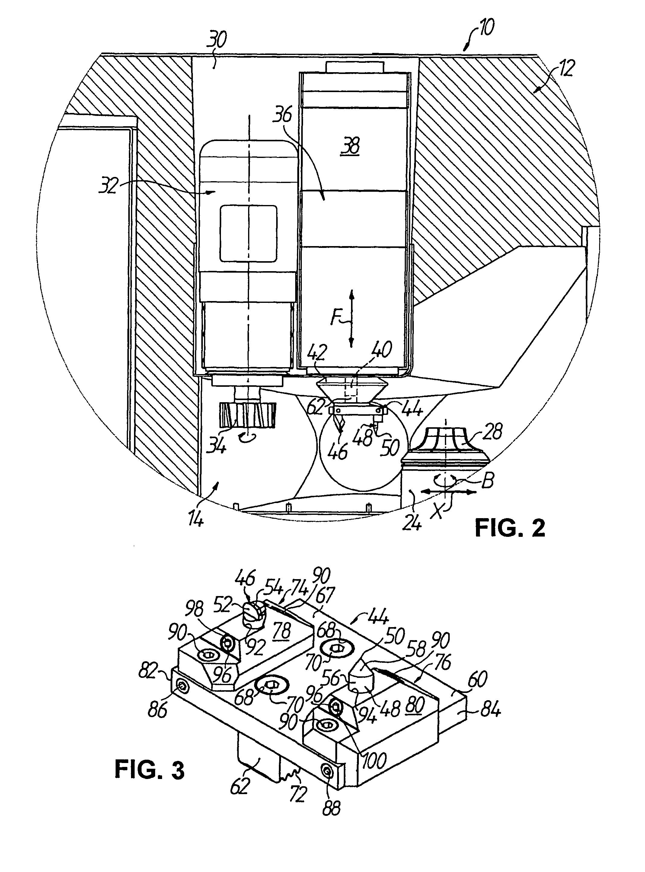
[0039]FIGS. 1 and 2 schematically show a CNC-controlled machine 10 in particular for the surface machining of spectacle lenses L made of plastic (see FIG. 7), in which the machine frame 12 which is cast in one piece from a polymer concrete is cut away in the region of the machine upper part in order to make it possible to see into a working space or machining area 14 of the machine 10. The machine 10 as such, without the engraving function, has already been described in the earlier German patent application DE 10 2005 021 638 A1 by the same Applicant, to which reference is additionally made here with regard to the basic structure of the machine and the function thereof.

[0040]On the left-hand side of the machining area 14 in FIG. 1, two guide rails 16 which extend parallel to one another in a (horizontal) width direction of the machine 10 are fixed to an upper mounting surface 18 of the machine frame 12 in FIG. 1. An X-carriage 20, which can be moved in a CNC-controlled...


PUM

PropertyMeasurementUnit
distanceaaaaaaaaaa
angleaaaaaaaaaa
frequenciesaaaaaaaaaa

Abstract

A machine for machining workpieces, for example plastic spectacle lenses, has a workpiece spindle which rotates the workpiece about a workpiece rotation axis, and a fast tool arrangement which moves a turning tool in the direction to and from the workpiece, wherein the workpiece spindle and the fast tool arrangement can moreover be moved relative to one another in a direction transverse to the workpiece rotation axis. A tool holder is connected to the fast tool arrangement and carries the turning tool. An engraving tool is spaced from the workpiece rotation axis and has an essentially point-shaped end facing towards the workpiece. The engraving tool can be moved in the direction of the workpiece and away therefrom in a highly dynamic manner via the tool holder, so that a marking can be produced on the workpiece in particular by a needling engagement of the engraving tool with the workpiece.

Description

TECHNICAL FIELD[0001]The present invention relates to a machine for machining optical workpieces, in particular plastic spectacle lenses. The invention also relates to a tool holder for such a machine.PRIOR ART[0002]In the machining of plastic spectacle lenses, there is usually a spectacle lens blank injection-molded from plastic, which has a standardised finished convex outer surface with a spherical, aspherical or progressive shape for example. The machining process serves to give the inner surfaces or prescription surfaces, which are usually concave, a spherical, aspherical, toric, atoric, progressive or free-form geometry (varifocal surfaces), depending on the desired optical effect. The typical conventional procedure when machining the inner surfaces comprises, after placing the spectacle lens blank with its outer surface on a block piece, a milling or turning (lathe) process in order to produce the optically active shape, usually followed by a fine grinding or polishing proces...

Claims


Application Information

Patent Timeline
Patent Type & Authority Patents(United States)
IPC IPC(8): B23P23/00
CPCB23B29/26B24B13/06B24B27/0076B44B3/04B24B13/046Y10T29/5154Y10S82/904Y10T82/2508Y10T29/5114Y10T82/25Y10T82/2524Y10T279/29Y10T29/5168Y10T29/5175Y10T279/17Y10T82/143Y10T82/148
Inventor MEYER, URSSAVOIE, MARC
Owner SATISLOH AG
Why Eureka
Try Eureka