Biological tissue motion trace method and image diagnosis device using the trace method

a biochemical tissue and motion trace technology, applied in the field of biochemical tissue motion trace method and image diagnosis device using the trace method, can solve the problems of loss of brightness, brightness, brightness change measured in the roi, and inability to obtain a sufficiently accurate evaluation index,

Active Publication Date: 2012-05-01
FUJIFILM HEALTHCARE CORP
View PDF17 Cites 27 Cited by
  • Summary
  • Abstract
  • Description
  • Claims
  • Application Information

AI Technical Summary

Benefits of technology

[0063]As described above, according to this embodiment, the coordinate of reference point 53a of ROI 53 after movement can be sequentially calculated with respect to the tissue movement by using the image correlation method, whereby it is possible to display ROI 53 along with the tissue movement. As a result, since the change of a relative position between the mark of ROI 53 and the tissue is avoidable, the ROI to be measured is certainly positioned within the mark of ROI 53. Therefore, reliability of evaluation index for measurement of ROI 53 is improved.

Problems solved by technology

However, the above conventional techniques are available only in evaluating the whole cardiac functions, while they are not designed to measure the moving state of the organs, i.e. movement of each tissue such as cardiac muscle.
Particularly, the conventional techniques of extracting the outline of cardiac ventricle with image processings and measuring the thickness of cardiac wall based on the outline are not always capable of acquiring a sufficiently accurate result.
As a result, reliability of evaluation indexes, such as a brightness, a brightness average, and a brightness change measured in the ROI is lost and those indexes become unavailable.

Method used


Image

  • Biological tissue motion trace method and image diagnosis device using the trace method
  • Biological tissue motion trace method and image diagnosis device using the trace method
  • Biological tissue motion trace method and image diagnosis device using the trace method

Examples


embodiment 1

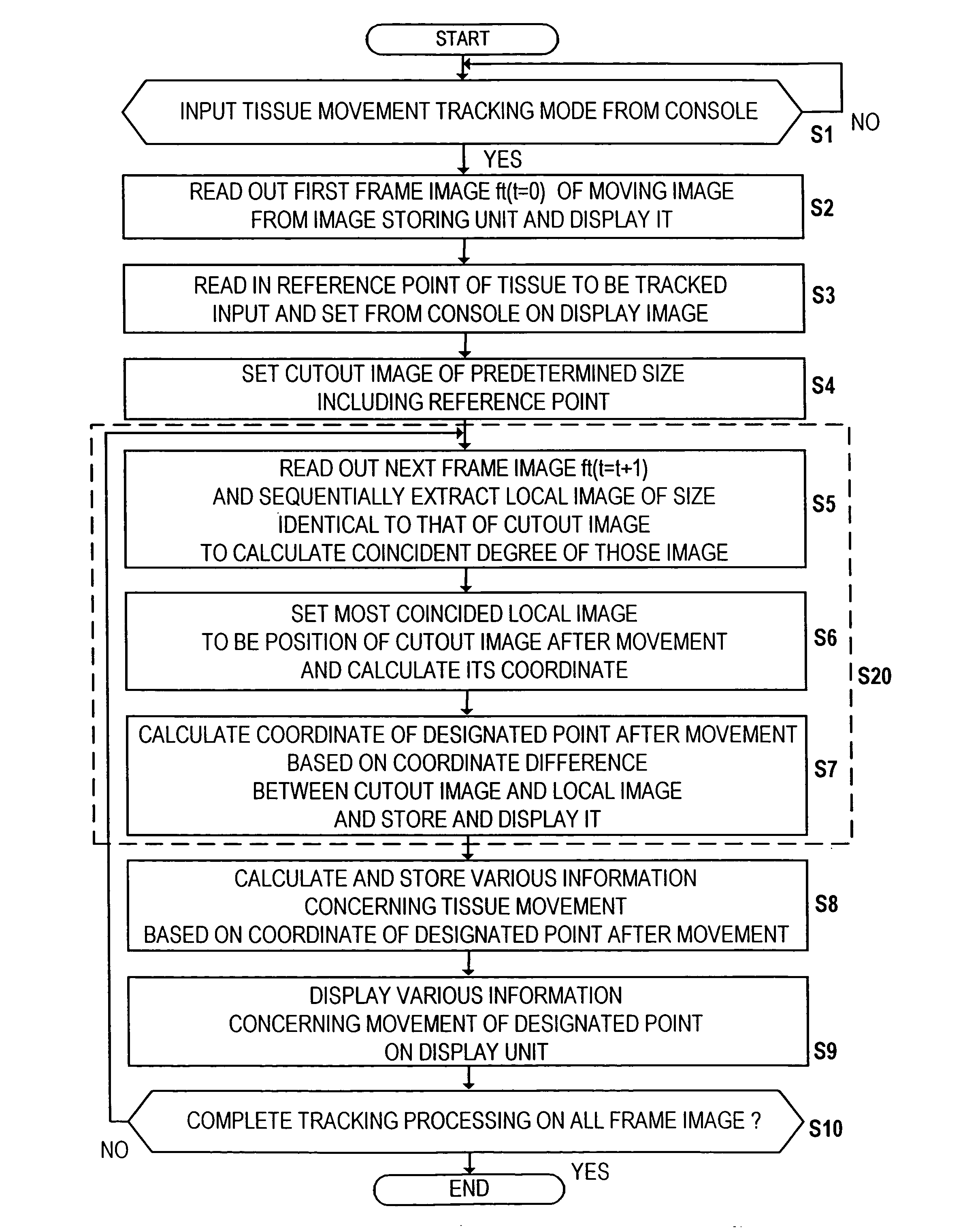
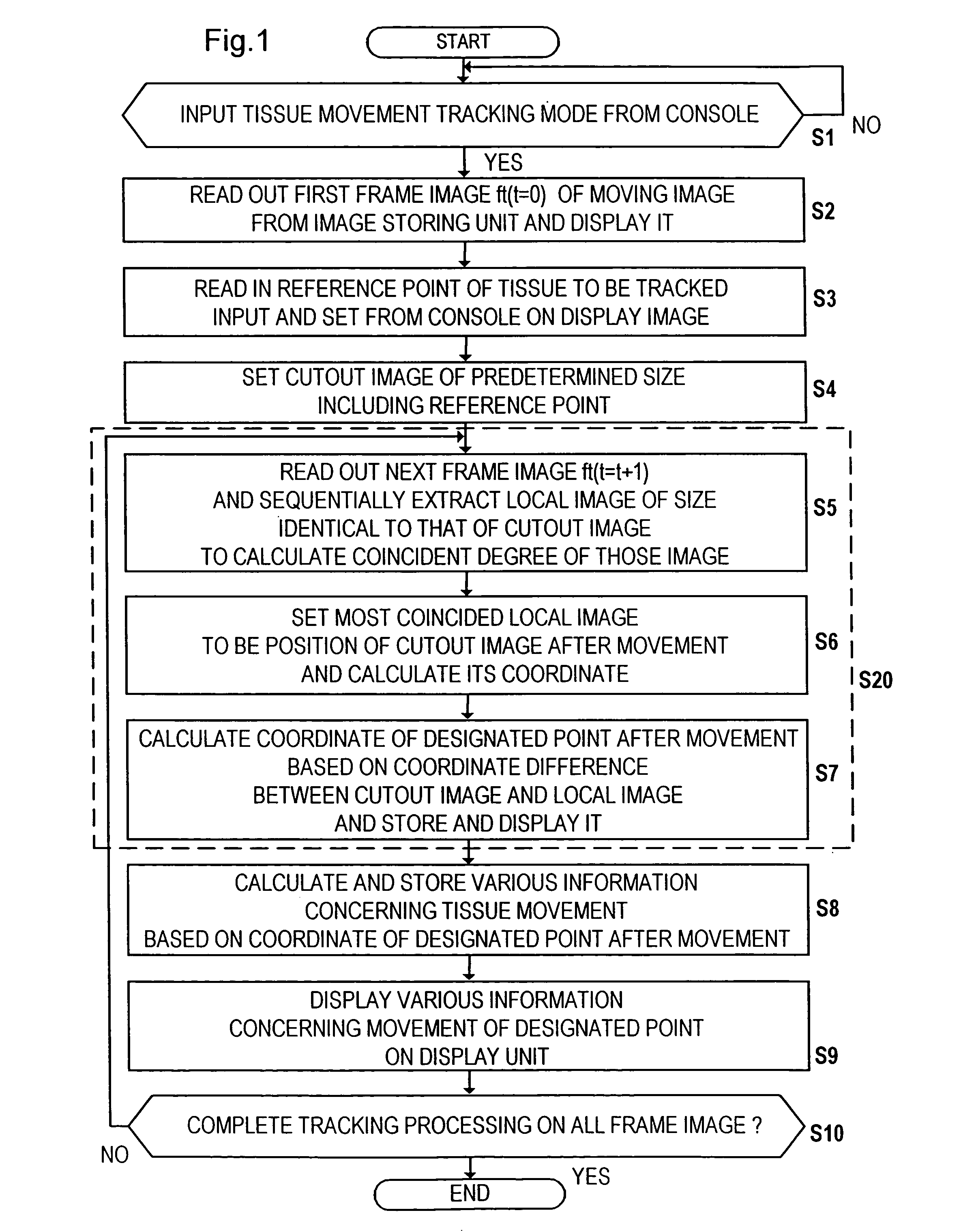
[0032]One embodiment of an image diagnostic apparatus which employs the tissue movement tracking method according to the present invention will be described with reference to FIGS. 1 to 4. FIG. 1 shows a procedure of the tissue movement tracking method according to the present embodiment, and FIG. 2 is a block diagram showing an image diagnostic apparatus which employs the tissue movement tracking method of FIG. 1. As shown in FIG. 2, the image diagnostic apparatus includes image storing unit 1 for storing a moving image formed by producing tomographic images of an object to be examined, display unit 2 capable of displaying the moving image, console 3 for inputting a command, automatic tracking unit 4 for tracking tissue movement in the moving image displayed on display unit 2, movement information calculating unit 5 for calculating various measured information based on a tracking result of automatic tracking unit 4, and signal line 6 connecting the above components. Image storing u...

embodiment 2

[0048]According to the above described embodiment of FIG. 1, every time tracking of the designated point in a one-frame image is finished (S7), various information concerning the tissue movement is calculated based on the movement of the designated point (S8) and the information is displayed on the display unit (S9). Meanwhile, the present invention is not limited thereto and it is also desirable to place the step S10 of FIG. 1 subsequent to the step S7 and execute the processings of steps S8 and S9 after tracking of the designated point is finished in images of all frames.

[0049]Here, a detailed example of image tracking processings based on the image correlation method will be described with reference to FIG. 11. For simplifying the explanation, in the shown example the size of cutout image 25 is represented as a portion including nine rectangular pixels and searchable area 26 is represented as a region including twenty-five pixels. That is, cutout image 25 shown in FIG. 11(a) is s...

embodiment 3

[0050]This embodiment is applicable to tissue tracking processings using a moving image obtained with an ultrasound imaging method. Particularly, it is designed to smooth the shift of a measured value obtained by tracking the tissue movement by storing an RF signal corresponding to the moving image and correcting the position of most coincided local image calculated based on the image correlation method using the RF signals.

[0051]FIG. 12 illustrates the embodiment wherein ultrasound diagnostic apparatus 17 is used as diagnostic imaging apparatus 7. An ultrasound diagnostic apparatus is an apparatus for conducting diagnosis on an object's disease or the like by transmitting an ultrasound wave into the object, receiving an ultrasound signal reflected at a tissue in the object, processing the received signal, and displaying an ultrasound image of the inside of the object based on the received signal.

[0052]The moving image and RF signals (signals obtained by performing reception process...


PUM


Abstract

A one frame image of a moving image formed by producing tomographic images of an object to be examined is displayed (S2), a mark is superposed on a designated portion of a tissue the movement of which is tracked in the displayed one frame image (S3), a cutout image of a size including the designated portion is set in the one frame image (S4), local images are searched in another frame images of the moving image and a local image of the identical size which is most coincided with the cutout image is extracted (S5,6), and a coordinate of the designated portion after movement is calculated based on a coordinate difference between the most coincided local image and the cutout image (S7), thereby the movement of tissue is quantitatively measured.

Description

TECHNICAL FIELD[0001]The present invention relates to a method of tracking movement of a tissue applied to an ultrasound diagnostic image, a magnetic resonance image, or an X-ray CT image, and to an image diagnostic apparatus using the tracking method and a technique of programming thereof.BACKGROUND TECHNIQUE[0002]Image diagnostic apparatuses such as an ultrasound diagnostic apparatus, a magnetic resonance imaging (MRI) apparatus, and an X-ray CT apparatus are designed to display a tomographic image and the like concerning an examining region of an object to be examined on a monitor for conducting diagnosis. For example, when circulatory organs such as a heart and a blood vessel and other moving organs are examined, movement of tissue structuring them is observed in a tomographic image to conduct diagnosis of functions of those organs.[0003]Particularly, diagnostic accuracy is expected to be further improved if the functions of the heart and the like can be quantitatively evaluated...

Claims


Application Information

Patent Timeline
Patent Type & Authority Patents(United States)
IPC IPC(8): A61B8/00A61B8/08G06T7/20
CPCA61B8/469G06T7/20A61B8/08G06T2207/30048G06T2207/30101
Inventor BABA, HIROTAKAMORI, OSAMU
Owner FUJIFILM HEALTHCARE CORP
Why Eureka
Try Eureka