Water removal features for PEMfc stack manifolds

a technology of stack manifolds and features, applied in the field of fuel cell stack water removal systems, can solve the problems of stack operation instability, performance degradation, and high cost of catalysts and precious metals, and achieve the effects of improving performance, improving efficiency, and improving stability

Active Publication Date: 2012-05-01
GM GLOBAL TECH OPERATIONS LLC
View PDF28 Cites 4 Cited by
  • Summary
  • Abstract
  • Description
  • Claims
  • Application Information

AI Technical Summary

Benefits of technology

[0030]One of the intended benefits of the present invention thus includes, without limitation, the removal of the liquid water from areas of the reactant channel exits and manifold walls that hinder gas flows and lead to instability in stack operation at low loads. It follows that this enhancement will also benefit freeze durability, reduce mal-distribution between cells, and improve fuel cell stack performance.

Problems solved by technology

The catalytic particles are typically costly precious metal particles.
These membrane electrode assemblies are relatively expensive to manufacture and require certain conditions, including proper water management and humidification, and control of catalyst fouling constituents such as carbon monoxide (CO), for effective operation.
As the water collects in liquid form in droplets, slugs, and films toward the exit of the stack, it tends to hinder the flow of the reactant gases, thus resulting in instability in stack operation and performance degradation.
This approach has been shown to significantly improve operational stability of the fuel cell stack, especially under low power conditions where uniform distribution of the reactants among individual cells is otherwise difficult to achieve.
Even with the improvement in water and gas transport within the flow field channels provided by hydrophilic coating, water management issues become a concern near the ends of the channels, where the various phases must transition into a region where the flow velocities and forces acting on the flow are quite different.
More specifically, a water film tends to form on the face of the outlet manifold wall which tends to cover over the end openings of the reactant channels, thus obstructing the gas flow.
However, under some low power operating conditions, the force of the moving gas stream may be insufficient to overcome the liquid film and that gas passage will be blocked.

Method used


Image

  • Water removal features for PEMfc stack manifolds
  • Water removal features for PEMfc stack manifolds
  • Water removal features for PEMfc stack manifolds

Examples


Embodiment Construction

[0018]The following description of the preferred embodiment(s) is merely exemplary in nature and is in no way intended to limit the invention, its application, or uses.

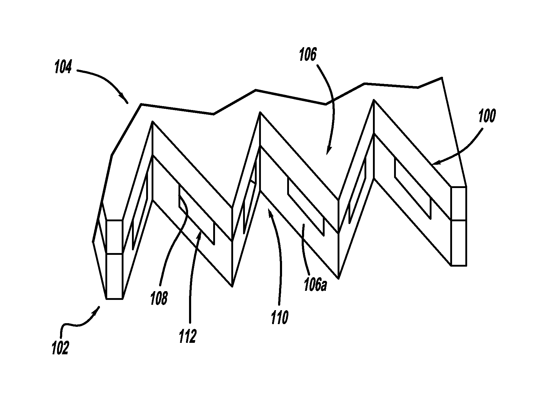
[0019]In accordance with the general teachings of the present invention, liquid water films can be moved away from the openings of the reactant channels by using capillary forces generated by certain geometric features incorporated into the bipolar plate assembly. It should be appreciated that the present invention can be practiced with stamped metallic bipolar plates as well as composite plastic bipolar plates, including those in stacked configurations. The bipolar plates of the present invention are especially useful in conjunction with fuel cells, such as but not limited to PEM fuel cells.

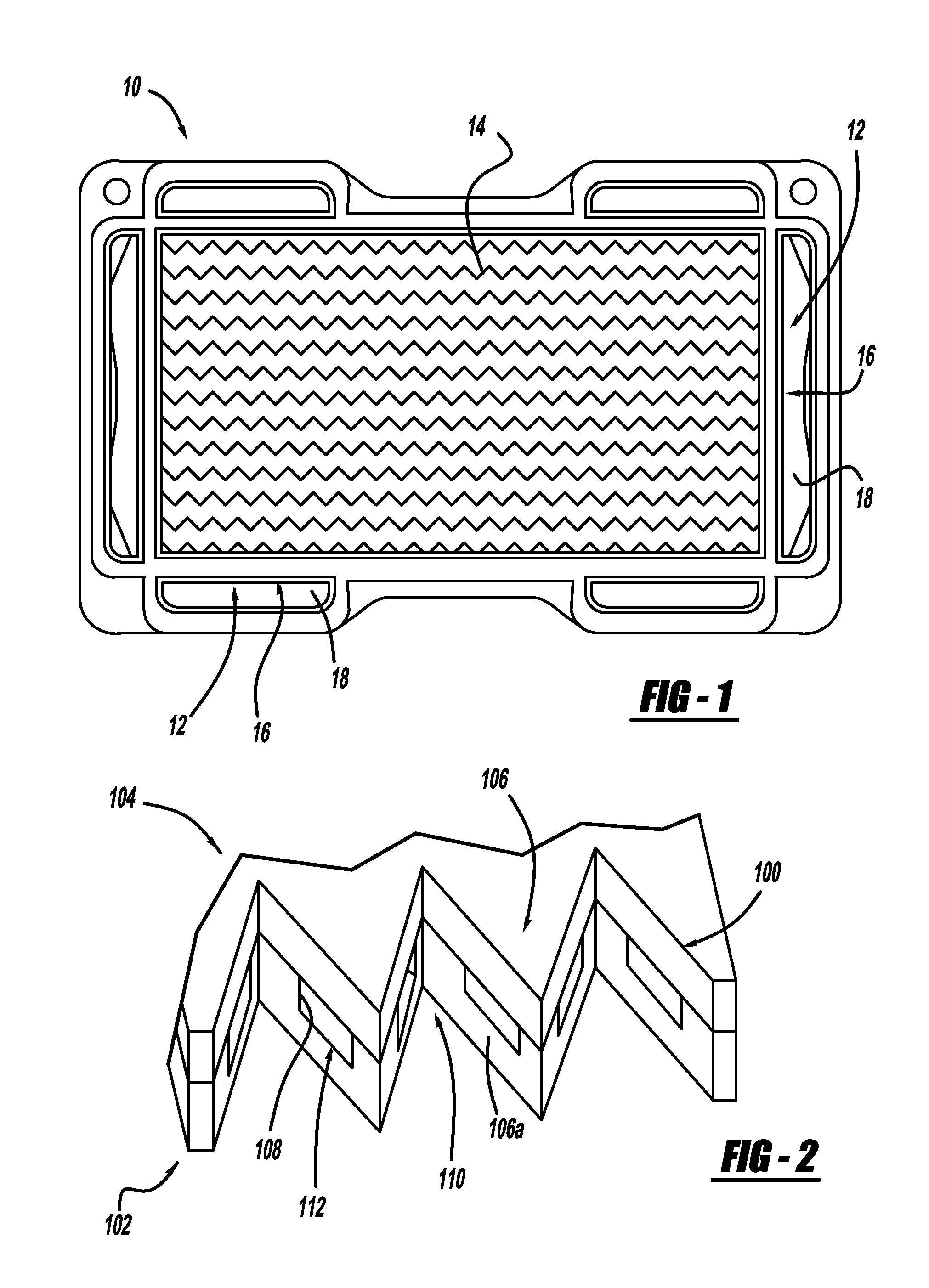
[0020]Referring to FIG. 1, there is shown a bipolar plate generally at 10, in accordance with the general teachings of the present invention. More specifically, the relative location of the ends 12 of the reactant outlet channels ...


PUM

PropertyMeasurementUnit
capillary forcesaaaaaaaaaa
lengthaaaaaaaaaa
hydrophilicaaaaaaaaaa

Abstract

A bipolar plate includes angled facets oriented to form V-shaped projections on the plate edge. Liquid leaving the reactant channels is drawn back into the V-shaped grooves of the projections, leaving no liquid to obstruct the channel exit openings. The bipolar plate includes one portion of the bipolar plate offset from another portion of the bipolar plate so as to expose the reactant channels. The liquid is drawn toward the end portions of the reactant channels by capillary forces, while the gas flows can exit near the beginning of the offset portion. A fuel cell stack includes angled facets that are rotated to lie in the plane of the bipolar plate edges. The edges are chamfered so the channel exit openings of the reactant channels are at the tip portions thereof, thus allowing the liquid to flow away from the channel exit openings and the gas to exit freely.

Description

FIELD OF THE INVENTION[0001]The present invention relates generally to fuel cell systems, and more particularly to water removal systems for fuel cell stacks.BACKGROUND OF THE INVENTION[0002]Fuel cells have been used as a power source in many applications. For example, fuel cells have been proposed for use in electrical vehicular power plants to replace internal combustion engines. In PEM-type fuel cells, hydrogen is supplied to the anode of the fuel cell and oxygen is supplied as the oxidant to the cathode. PEM fuel cells include a membrane electrode assembly (MEA) comprising a thin, proton transmissive, non-electrically conductive solid polymer electrolyte membrane having the anode catalyst on one of its faces and the cathode catalyst on the opposite face. The MEA is sandwiched between a pair of electrically conductive elements, sometimes referred to as the gas diffusion media components, that: (1) serve as current collectors for the anode and cathode; (2) contain appropriate open...

Claims


Application Information

Patent Timeline
Patent Type & Authority Patents(United States)
IPC IPC(8): H01M8/06H01M8/04
CPCH01M8/0254H01M8/0258H01M8/04179H01M8/0263Y02E60/50H01M8/241H01M8/2483
Inventor WHITEHEAD, LEE C.FALTA, STEVEN R.TRABOLD, THOMAS A.OWEJAN, JON P.TIGHE, THOMAS W.
Owner GM GLOBAL TECH OPERATIONS LLC
Why Eureka
Try Eureka