Interlocking masonry blocks

a technology of interlocking masonry and blocks, which is applied in the field of masonry blocks, can solve the problems of insufficiently addressing the problem of labor cost, affecting the efficiency of workers, and introducing fatigue, physical strain, etc., so as to reduce labor costs and the chance of worker strain or injury, and reduce the time to complete

Active Publication Date: 2012-05-08
MAGUINNESS ELIZABETH
View PDF18 Cites 15 Cited by
  • Summary
  • Abstract
  • Description
  • Claims
  • Application Information

AI Technical Summary

Benefits of technology

[0031]The vertically-oriented rebar within the vertical channels along the length of the wall does not require excessive lifting of the masonry blocks of the present invention by workers, because the open channels of each end portion admit the positioning of the masonry block around fixed vertical rebar. A castable cement, concrete, or grout is then poured into the vertical channels and in the process also flows into and through the horizontal channels. The result is a wall having a beneficial combination of superior strength, simplified fabrication, and reduced labor costs over structures found in the prior art.OBJECTS OF THE INVENTION
[0032]Accordingly, it is an object of this disclosure to provide improved interlocking masonry blocks that so that an outward face of a structure made with the masonry blocks have a mortar-like gap located between each of the masonry blocks.
[0033]It is a further object of this disclosure to provide the means for assembling structures using interlocking masonry blocks that reduce labor costs and the chance for worker strain or injury, increase worker efficiency, and reduce time to complete the project.

Problems solved by technology

Because of the skill required, and additional time in preparing mortar and applying it to each block, construction costs due to labor can be substantial.
The repetitive motions of lifting of the many blocks that comprise a completed wall requires exertion and consumes time from the worker, and introduces fatigue, physical strain, and a risk of injury.
None of the prior art adequately addresses this problem.
This additional effort is obtained entirely through manual labor incurred with the placement of each masonry block, and the cumulative effect is a significant cost in time and labor.

Method used


Image

  • Interlocking masonry blocks
  • Interlocking masonry blocks
  • Interlocking masonry blocks

Examples


Embodiment Construction

[0050]In this application the term “masonry block” or simply “block” refers to any suitable masonry unit including bricks, clay, or concrete blocks that are shaped in the preferred configurations of this disclosure.

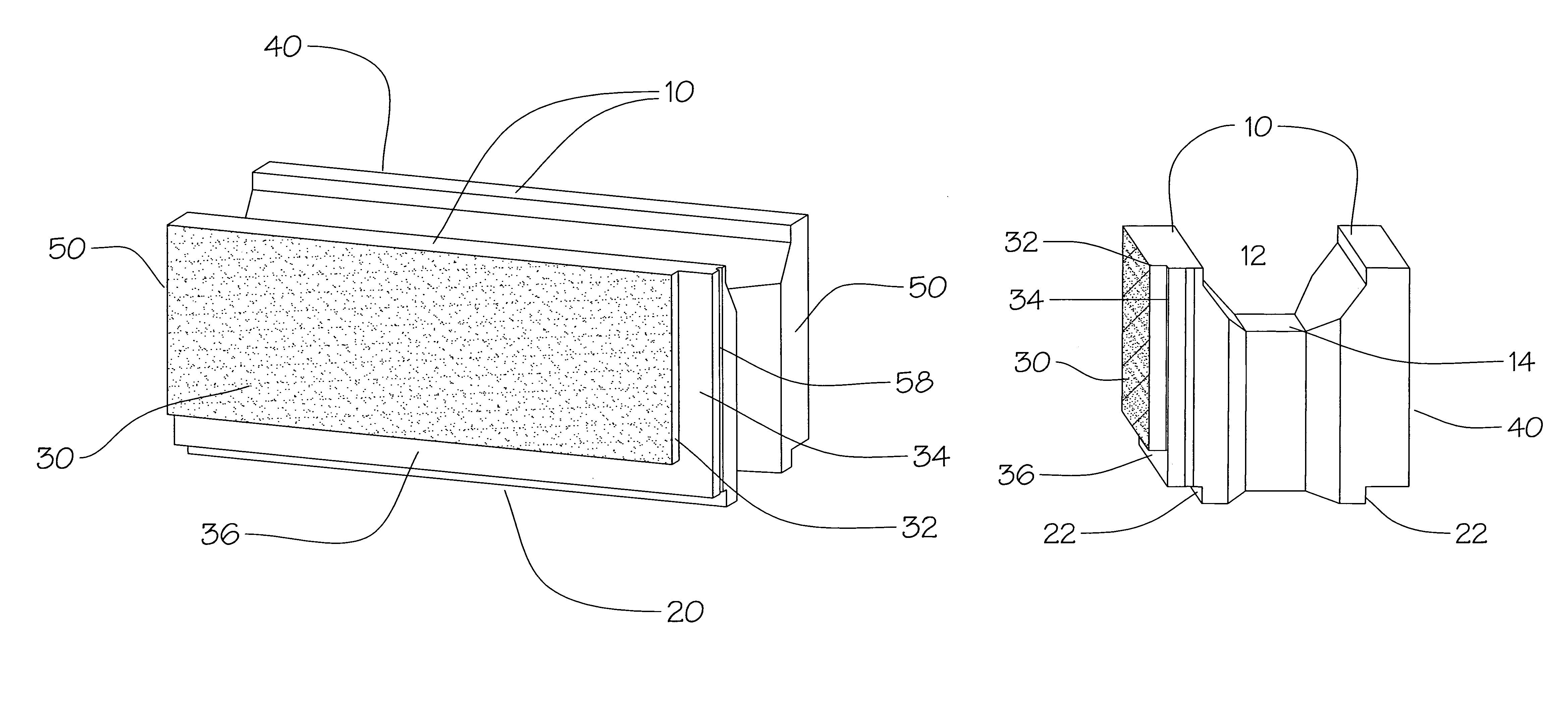
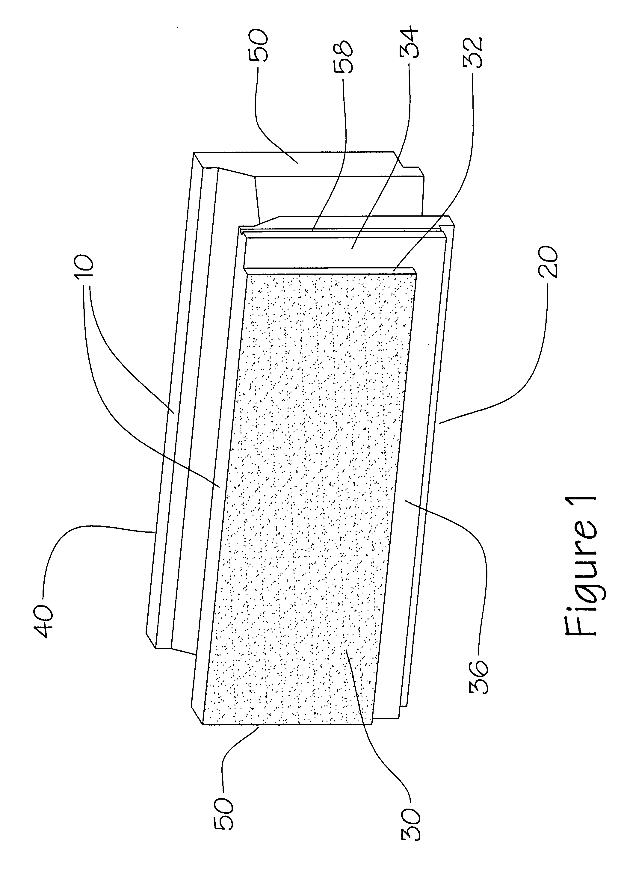
[0051]The present invention provides a block useful in the construction of walls and structures that is shaped in the general form of a rectangular solid. FIG. 1 illustrates the basic block 1 according to the invention which comprises a contoured top portion 10, a flat bottom portion 20, a front face portion 30, a rear face portion 40, and two end portions 50.

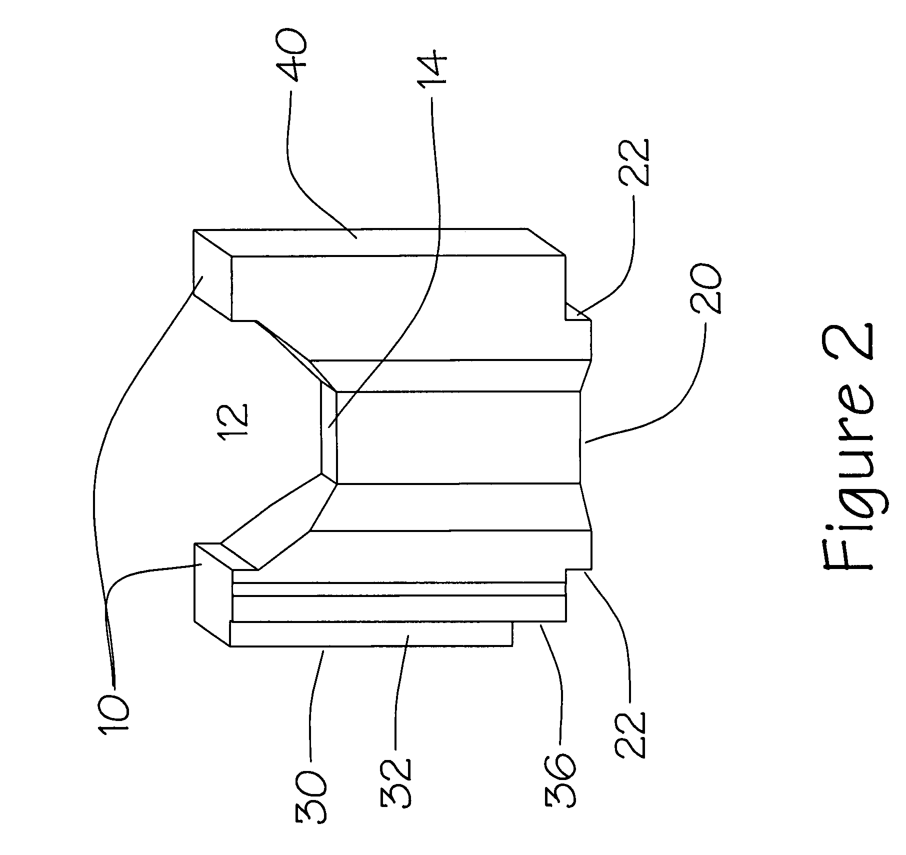
[0052]There is a single horizontal channel 12 extending along the entire length dimension of the block, as illustrated in FIG. 2 and FIG. 3, where the channel is open coincident with the top portion 10 of the block. The channel has a floor 14 where the uppermost point is preferably disposed between about 20% to 50% of the height dimension of the block. The channel 12 at its widest point has a preferred width of betwe...


PUM


Abstract

The present invention provides a block useful in the construction of walls and structures that is shaped in the general form of a rectangular solid. A horizontal channel extends along the entire length dimension of the block, open coincident with the top of the block. An open vertical channel associated with each end faces outwards toward an adjacent masonry block end. A protruding portion extends from the flat bottom with the same width of the open channel on the top, so that an interlocking connection is formed. A protruding rectangular portion is optionally incorporated into the front face portion, and also optionally into the rear face portion, leaving a recess along one end, and along the top, so that when assembled into a wall, the recessed parts of the face portion give the appearance of mortar joints. Vertical and horizontal rebar may be set within the aligned channels of the blocks when assembled into a wall. The blocks do not require excessive lifting when assembled to a wall or structure to clear vertically aligned set rebar.

Description

CROSS REFERENCE TO RELATED APPLICATIONS[0001]Not applicable.STATEMENT REGARDING FEDERALLY SPONSORED RESEARCH OR DEVELOPMENT[0002]Not applicable.REFERENCE TO MICROFICHE APPENDIX[0003]Not applicable.FIELD OF THE INVENTION[0004]This invention relates generally to masonry blocks. More specifically, the invention relates to novel interlocking masonry blocks that readily form continuous wall sections with mortar-less joints that present the appearance of mortared joints.BACKGROUND OF THE INVENTION[0005]Concrete block constructions of the prior art are made of individual blocks which are conventionally rectangular, and which generally have one or more cavities or channels through the blocks from their top to bottom. During their use in fabricating structures, a layer of mortar is applied onto a foundation, and a course of closely spaced blocks are laid onto the mortar layer, with additional mortar applied between the contiguous block ends. Another layer of mortar is applied to the top of t...

Claims


Application Information

Patent Timeline
Patent Type & Authority Patents(United States)
IPC IPC(8): E04B2/46
CPCE04B2/30E04B2/40E04B2002/0269
Inventor BANOVA, ALDO
Owner MAGUINNESS ELIZABETH
Why Eureka
Try Eureka