
Data transmission method in wireless mesh network and A-MSDU format

a data transmission and wireless mesh network technology, applied in the field of wireless local access networks, can solve the problems of inconvenient format of a-msdu in accordance with ieee 802.11n, the inability to utilize various ht phy/mac characteristics such as frame aggregation, and the opposition of mps

Active Publication Date: 2012-05-08
LG ELECTRONICS INC
View PDF11 Cites 28 Cited by
  • Summary
  • Abstract
  • Description
  • Claims
  • Application Information

AI Technical Summary

Benefits of technology

The invention provides a method for transmitting data in a wireless mesh network using a frame aggregation technique. The method allows multiple data frames to be transmitted between wireless stations in a mesh network using a single mesh peer link. The method also provides an A-MSDU format for efficiently aggregating data frames in the network. The technical effects of the invention include improved data transmission efficiency and utilization of high throughput PHY / MAC characteristics in wireless mesh networks.

Problems solved by technology

When the MPs set up the mesh peer link in accordance with the existing protocol, the MP having set up the mesh peer link cannot know whether the opposite MP should have the capability related to the HT service (for example, support the frame aggregation), and thus cannot utilize various HT PHY / MAC characteristics such as the frame aggregation.
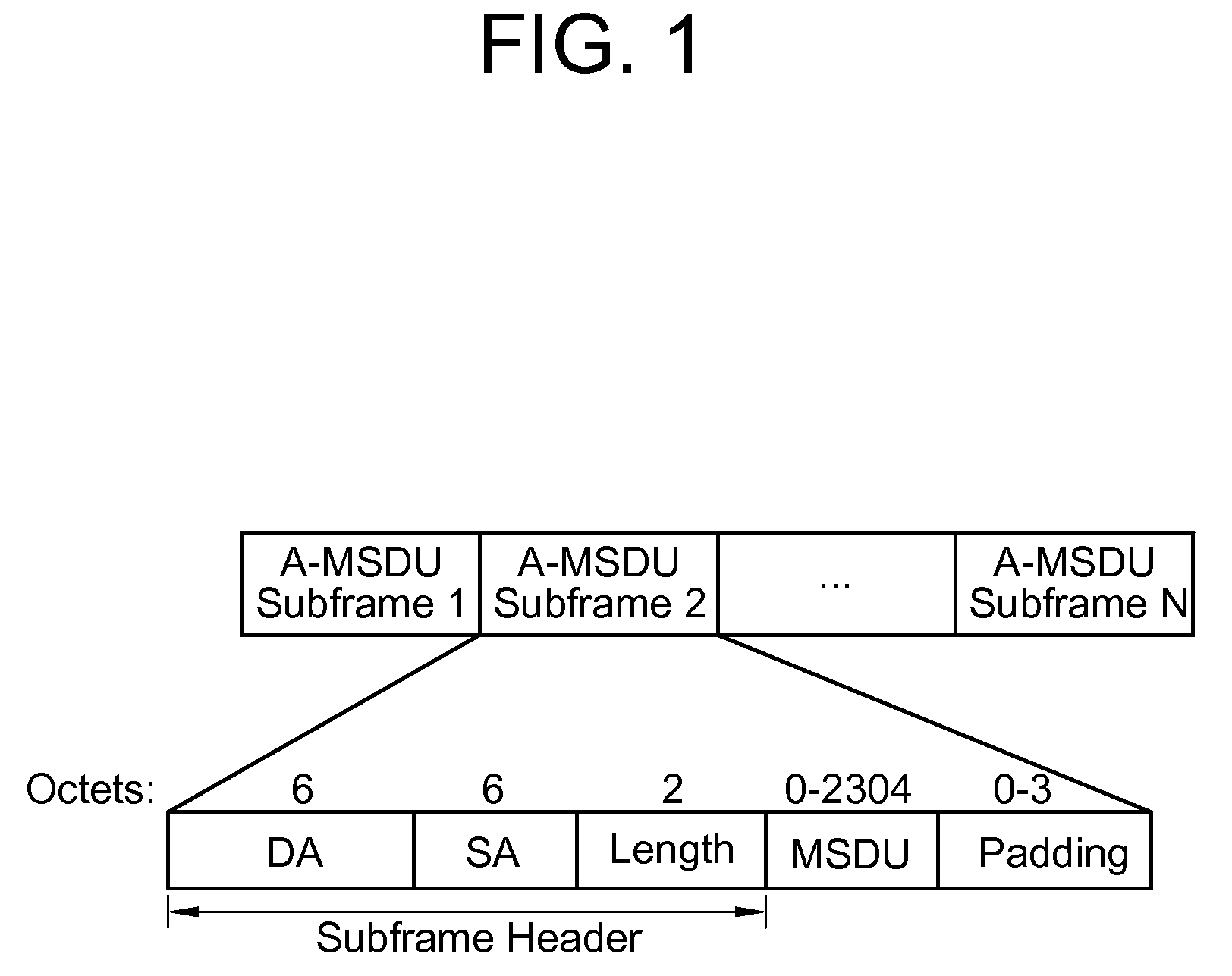
And, the format of the A-MSDU in accordance with the IEEE 802.11n is not suitable as the format of the A-MSDU for aggregating plural MSDUs used in the wireless mesh network.
However, since the wireless mesh network is designed to transmit data between wireless stations (for example, mesh points (MPs)) performing a relation function, the data transmitted through the mesh peer link may not have the same source station and / or the destination station.

Method used


Image

  • Data transmission method in wireless mesh network and A-MSDU format
  • Data transmission method in wireless mesh network and A-MSDU format
  • Data transmission method in wireless mesh network and A-MSDU format

Examples


Embodiment Construction

[0029]Hereinafter, an embodiment of the invention will be described with reference to the accompanying drawings.

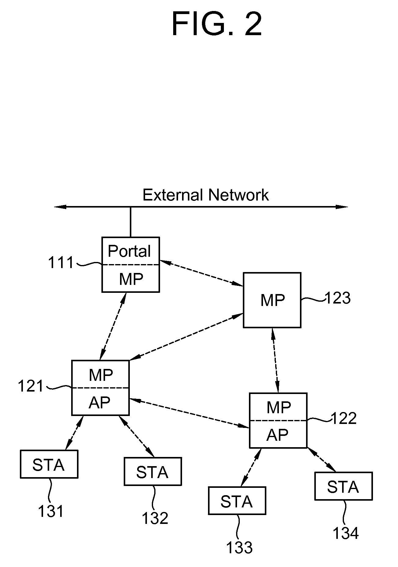
[0030]FIG. 2 is a diagram illustrating a configuration of a wireless mesh network. A wireless mesh network has a unique mesh identifier, which is used as a title for identifying a group of MPs constituting the wireless mesh network. A method of giving the mesh identifier is not limited.

[0031]Referring to FIG. 2, the wireless mesh network includes one or more STAs 131, 132, 133, and 134 and one or more wireless stations, that is, MPs 110, 121, 122, and 123. Reference numerals 121 and 122 indicate MPs performing the function of an AP, that is, MAPs, since the STAs 131, 132, 133, and 134 associated therewith exist. Reference numeral 121 indicates an MP connected to an external network by wired or by wireless, which is called a mesh portal.

[0032]The STAs 131 to 134 are optional functional mediums including a medium access control interface and a physical layer interface for wi...


PUM


Abstract

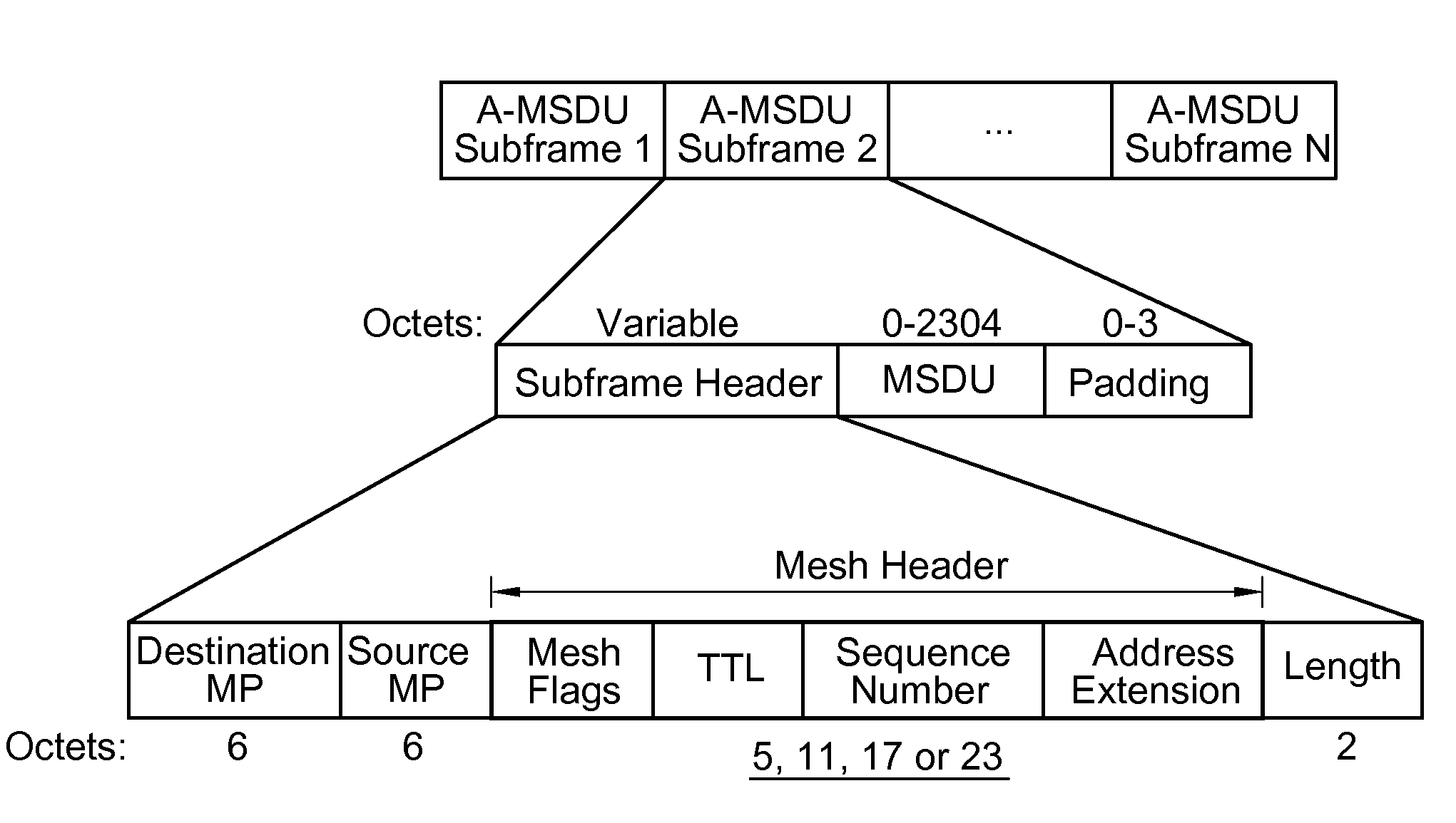
Provided are a method for transmitting data in wireless mesh networks and A-MSDU format for the method. In the method, in case the receiving MPs of all of the plural MSDUs to be transmitted are identical, a transmitting MP generates an A-MSDU using the plural MSDUs and transmits the A-MSDU to the receiving MP. The A-MSDU includes a plurality of A-MSDU sub-frames each of which includes a sub-frame header unit, an MSDU unit for containing data of each of the plural MSDU, and a padding unit for making each A-MSDU sub-frame a multiple of 4 octets in length. The sub-frame header unit comprises a mesh DA field for specifying an MAC address of the destination MP of the data contained in the MSDU unit, a mesh SA field for specifying an MAC address of the source MP of the data contained in the MSDU unit, and a mesh header field for containing information of the mesh header of each of the plural MSDUs.

Description

CROSS-REFERENCE TO RELATED PATENT APPLICATIONS[0001]This application claims the benefit of Korean Patent Application No. 10-2007-0113534 filed on Nov. 8, 2007 in the Korean Intellectual Property Office, the disclosure of which is incorporated herein in its entirety by reference.BACKGROUND[0002]1. Field of the Invention[0003]The present invention relates to a wireless local access network (WLAN), and more particularly, to a data transmission method in a wireless mesh network and a format of an aggregate-medium access control service data unit (A-MSDU) used in the data transmission method.[0004]2. Description of the Related Art[0005]With the recent development of information communication technology, a variety of wireless communication technology has been developed. A WLAN is the technology permitting wireless access to Internet in home or companies or specific service areas by the use of portable terminals such as a personal digital assistant (PDA), a laptop computer, and a portable ...

Claims


Application Information

Patent Timeline
Patent Type & Authority Patents(United States)
IPC IPC(8): H04W4/00H04L12/56H04L12/28
CPCH04W28/06H04W84/18
Inventor SEOK, YONG HOSAFONOV, ALEXANDER A.
Owner LG ELECTRONICS INC
Learn More