Drawing apparatus

a technology of drawing apparatus and drawing board, which is applied in the field of drawing apparatus, can solve the problems of affecting the yield of printed circuit boards, bitmap image data, and deteriorating access efficiency, and achieve the effect of reliably reducing the size of compressed data of bitmap image data

Active Publication Date: 2012-05-08
ADTEC ENG
View PDF7 Cites 6 Cited by
  • Summary
  • Abstract
  • Description
  • Claims
  • Application Information

AI Technical Summary

Benefits of technology

[0009]An object of the present invention is to solve the foregoing problem. Another object of the present invention is to provide a drawing apparatus which can reduce the size of compressed data of bitmap image data reliably and which can deal with the compressed data efficiently enough to create an exposure pattern rapidly.
[0014]It is possible to reduce the size of compressed data of bitmap image data reliably and it is also possible to deal with the compressed data efficiently enough to create an exposure pattern rapidly.

Problems solved by technology

However, since DRAMs are efficient for burst accesses, the accessing efficiency deteriorates when the bitmap image data are stored into the DRAM.
In a drawing apparatus as an exposure system, the yield in manufacturing printed circuit boards is affected by an error of one bit.
Therefore, irreversible compression cannot be applied to compression and expansion of bitmap image data between a cache and a DRAM.
According to such a method, however, the size of compressed data may be larger than the size of its original data when there is a particular relationship between the compression unit size and the pattern of the bitmap image data.
The efficiency in access to the DRAM cannot be always improved.

Method used


Image

  • Drawing apparatus
  • Drawing apparatus
  • Drawing apparatus

Examples


first embodiment

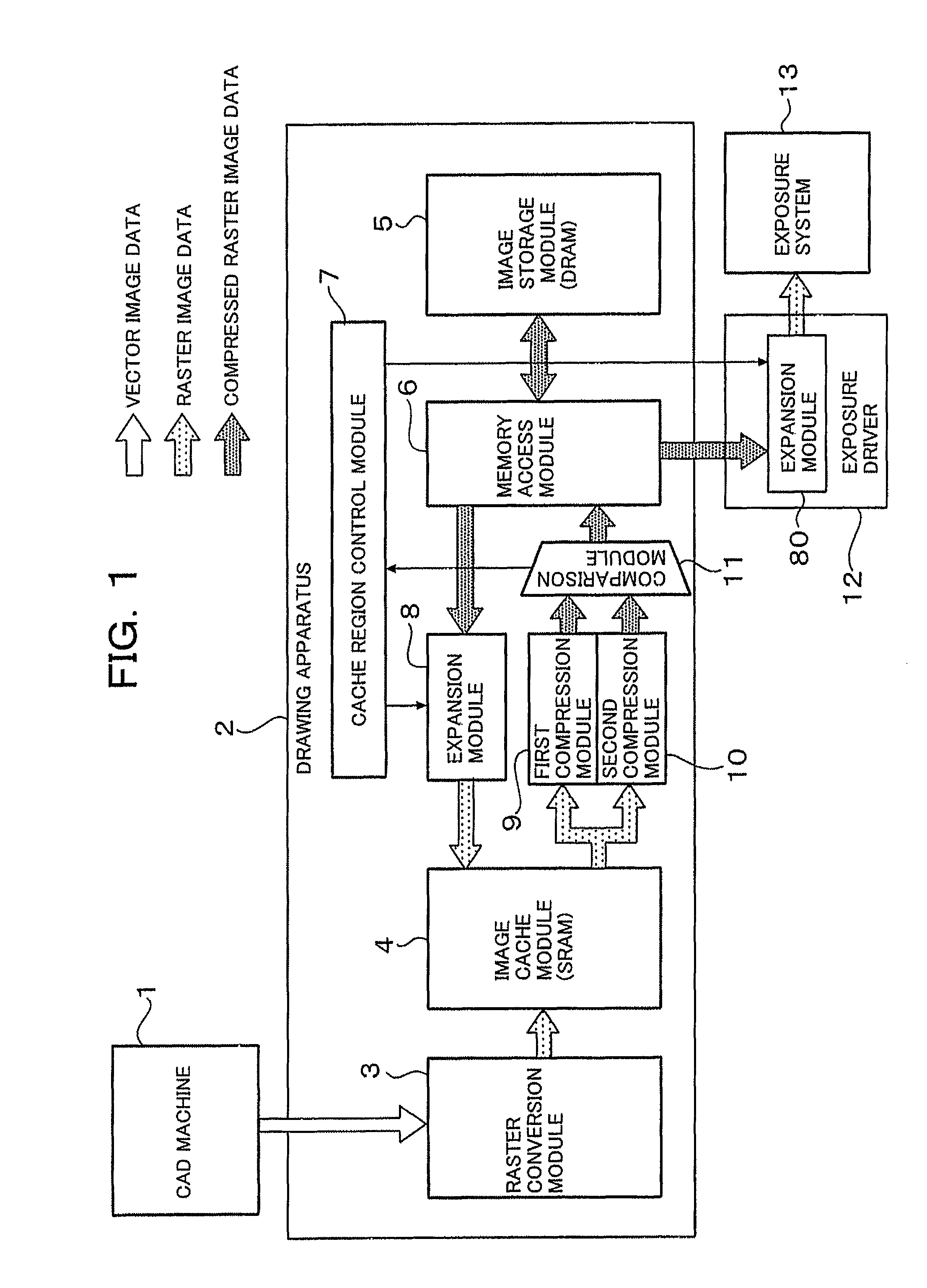
[0020]FIG. 1 is a diagram showing the configuration of a first embodiment of the present invention.

[0021]A drawing apparatus 2 surrounded by a rectangle in FIG. 1 has a raster conversion processing module 3, an image cache module (SRAM) 4, a first compression module 9, a second compression module 10, a comparison module 11, a memory access module 6, an image storage module (DRAM) 5, a cache region control module 7 and an expansion module 8. The raster conversion processing module 3 is connected to a CAD machine 1. The memory access module 6 and the cache region control module 7 are connected to an expansion module 80. The expansion module 80 is connected to an exposure system 13.

[0022]Next, the operation of the CAD drawing apparatus according to this embodiment will be described.

[0023]The CAD machine 1 supplies data (vector image data) to the raster conversion processing module 3 of the drawing apparatus 2. By the supplied vector image data, wiring patterns described in a design dra...

second embodiment

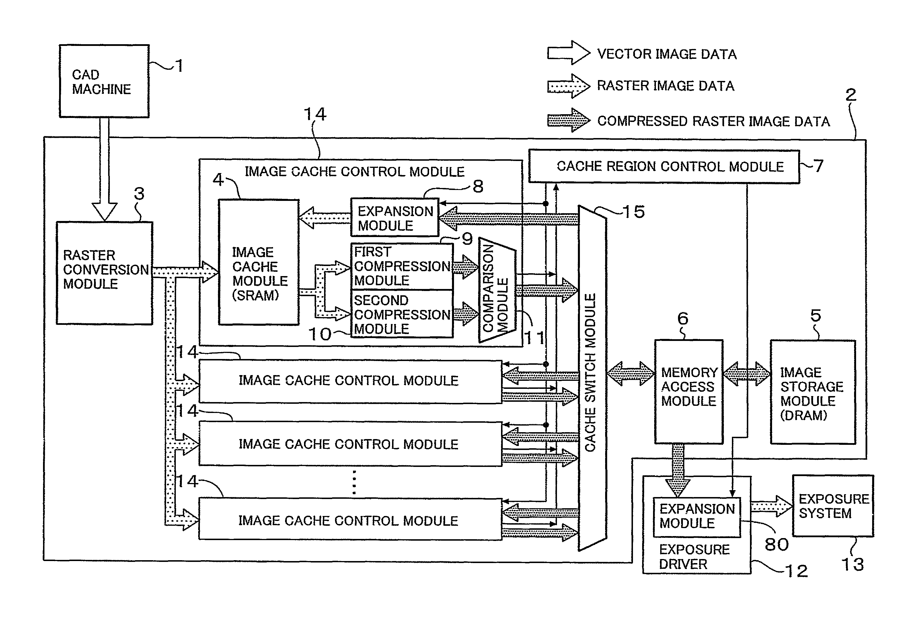
[0048]FIG. 3 is a configuration diagram of a drawing apparatus according to a second embodiment of the present invention.

[0049]The drawing apparatus according to the second embodiment has a plurality of image cache control modules 14. Each image cache control module 14 includes the image cache module 4, the expansion module 8, the first compression module 9, the second compression module 10 and the comparison module 11 shown in FIG. 1. Further, a cache switch module 15 is provided between the plurality of image cache control modules 14 and the memory access module 6.

[0050]The operation of the drawing apparatus according to the second embodiment differs from that according to the first embodiment as follows. That is, a bitmap image in another cache region than a cache region expanded in the image cache module 4 may be generated by the raster conversion processing module 3. In this case, a cached image in the expanded cache region is not written back into the image storage module 5, b...


PUM


Abstract

A drawing apparatus which can create an exposure pattern rapidly. The drawing apparatus has a raster conversion processing module for converting vector images as wiring patterns into bitmap image data, an image cache module for temporarily storing a predetermined-size cached image supplied from the raster conversion processing module, a first compression module for compressing the cached image stored in the image cache module, a second compression module for compressing the cached image stored in the image cache module in a compression ratio differing from that of the first compression module, a comparison module for comparing data sizes of compressed data generated by the first and second compression modules and selecting one having a smaller data size, a memory access module for writing the compressed data selected by the comparison module, into a storage module, and a cache region control module for controlling a compression status of the cached image.

Description

FIELD OF THE INVENTION[0001]The present invention relates to a drawing apparatus by which a wiring pattern designed by a CAD or the like is converted into an exposure pattern (bitmap image data) in a process for manufacturing a printed circuit board.BACKGROUND OF THE INVENTION[0002]A direct exposure system which is one of exposure systems is a system for exposing a printed circuit board to draw a wiring pattern without using any mask. For the exposure, the direct exposure system uses a drawing apparatus by which the wiring pattern designed by a CAD or the like is converted into an exposure pattern matched to the exposure system (this conversion will be referred to as “raster conversion”). The wiring pattern is composed of a set of line segments (vector images) showing the outline of a figure and expressed in a vector format. On the other hand, the exposure pattern is composed of a set of binary (for example, white and black) data (bitmap image data) having a size corresponding to ex...

Claims


Application Information

Patent Timeline
Patent Type & Authority Patents(United States)
IPC IPC(8): G06K9/46
CPCG06F12/0804G09G5/36G09G5/393G09G2340/02G09G2360/121
Inventor FUNATSU, TERUNOBUOSAKA, YOSHIHISAIKEGAMI, HITOSHI
Owner ADTEC ENG
Why Eureka
Try Eureka