Multi-core ferrule and optical fiber connection structure

a multi-core ferrule and optical fiber technology, applied in the direction of optics, bundled fibre light guides, instruments, etc., can solve the problems of difficult uniform protrusion, inability to ensure pc connection, optical loss, etc., and achieve the effect of reducing optical loss and low cos

Active Publication Date: 2012-05-08
ADTEC ENG
View PDF11 Cites 15 Cited by
  • Summary
  • Abstract
  • Description
  • Claims
  • Application Information

AI Technical Summary

Benefits of technology

[0013]An object of the present invention is to provide a multi-core ferrule and an optical fiber connection structure minimizing optical loss at low cost.
[0019]The present invention minimizes optical loss while ensuring the PC connection and is provided at low cost.

Problems solved by technology

By the way, if there is a gap between the end surfaces of the optical fibers, Fresnel reflection occurs at the interface between the optical fiber and the air in the gap, which results in optical loss.
According to the single / single-core connection structure disclosed in the Japanese Patent Laid-Open Publication No. 2002-333528, however, it is difficult to uniformly protrude respective optical fibers composing the optical fiber bundle, and therefore the PC connection cannot be assured.
According to the single / single-core connection structure disclosed in the Japanese Patent Laid-Open Publication No. 2000-180664, the ferrules have flat end surfaces and the sleeve needs to be formed with high precision, which results in a rise in production cost for assuring the connection.

Method used


Image

  • Multi-core ferrule and optical fiber connection structure
  • Multi-core ferrule and optical fiber connection structure
  • Multi-core ferrule and optical fiber connection structure

Examples


example 1

[0042]Hereinafter, Example 1 of the present invention is explained with several experiments and comparative experiments.

Experiment 1

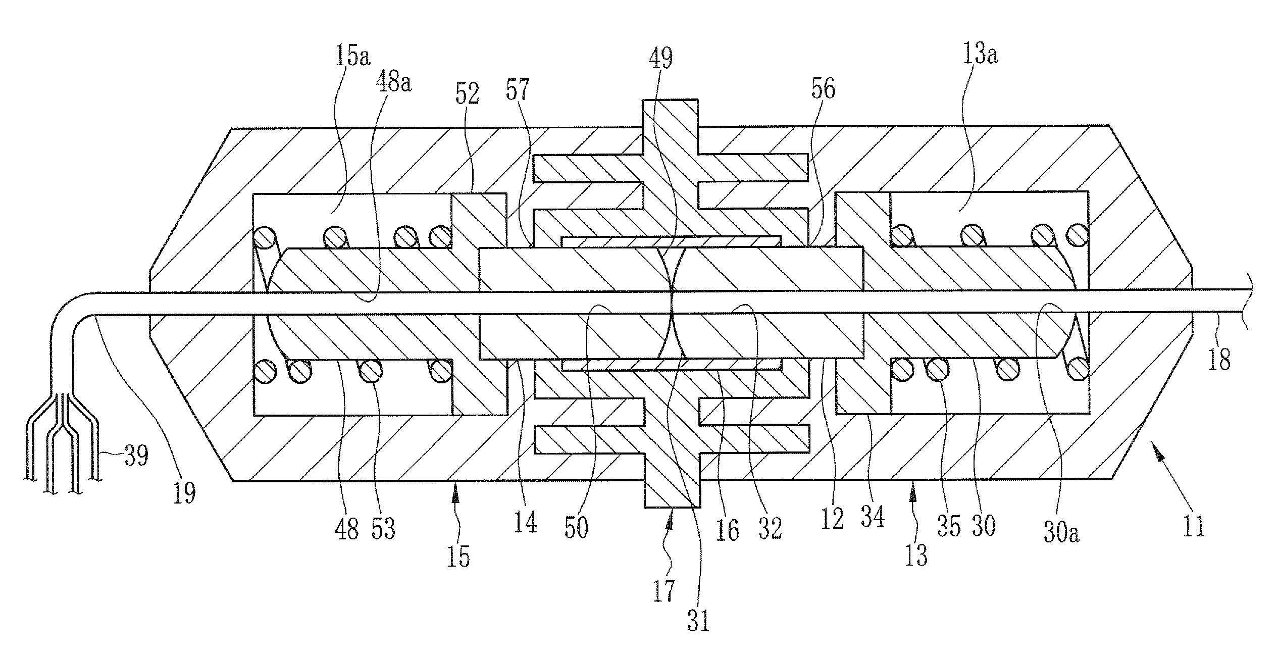
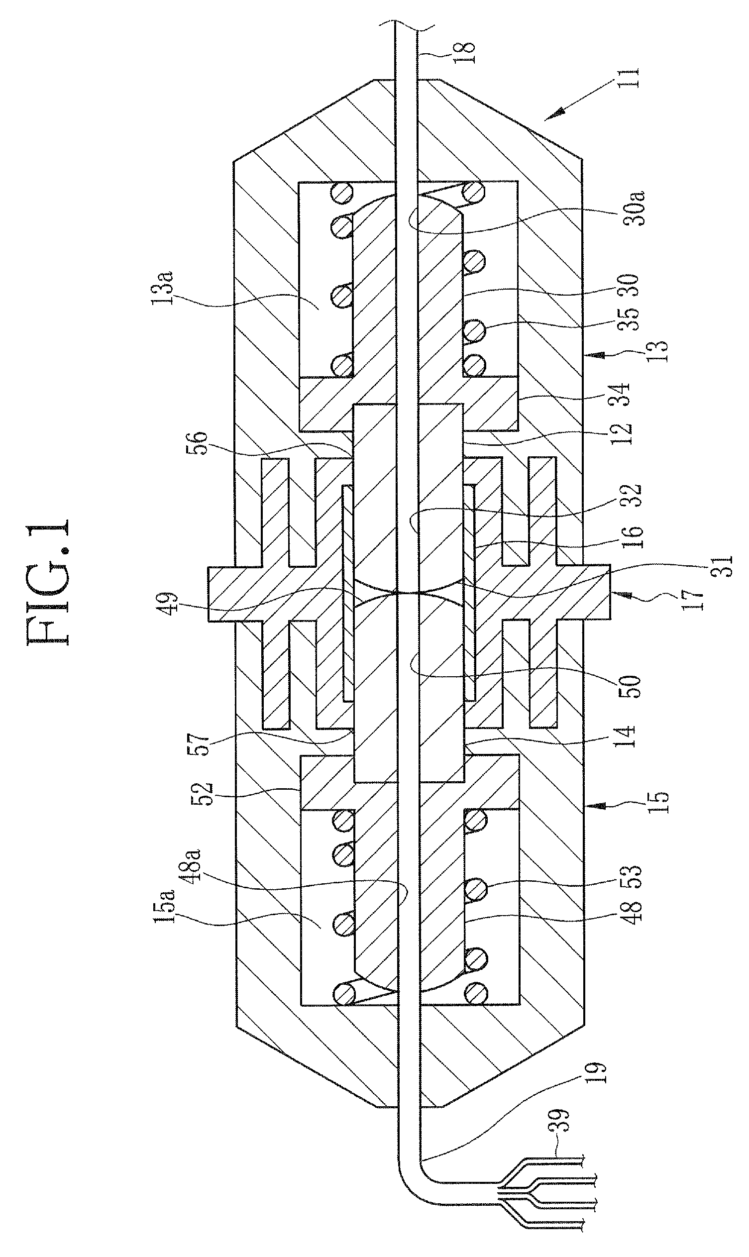
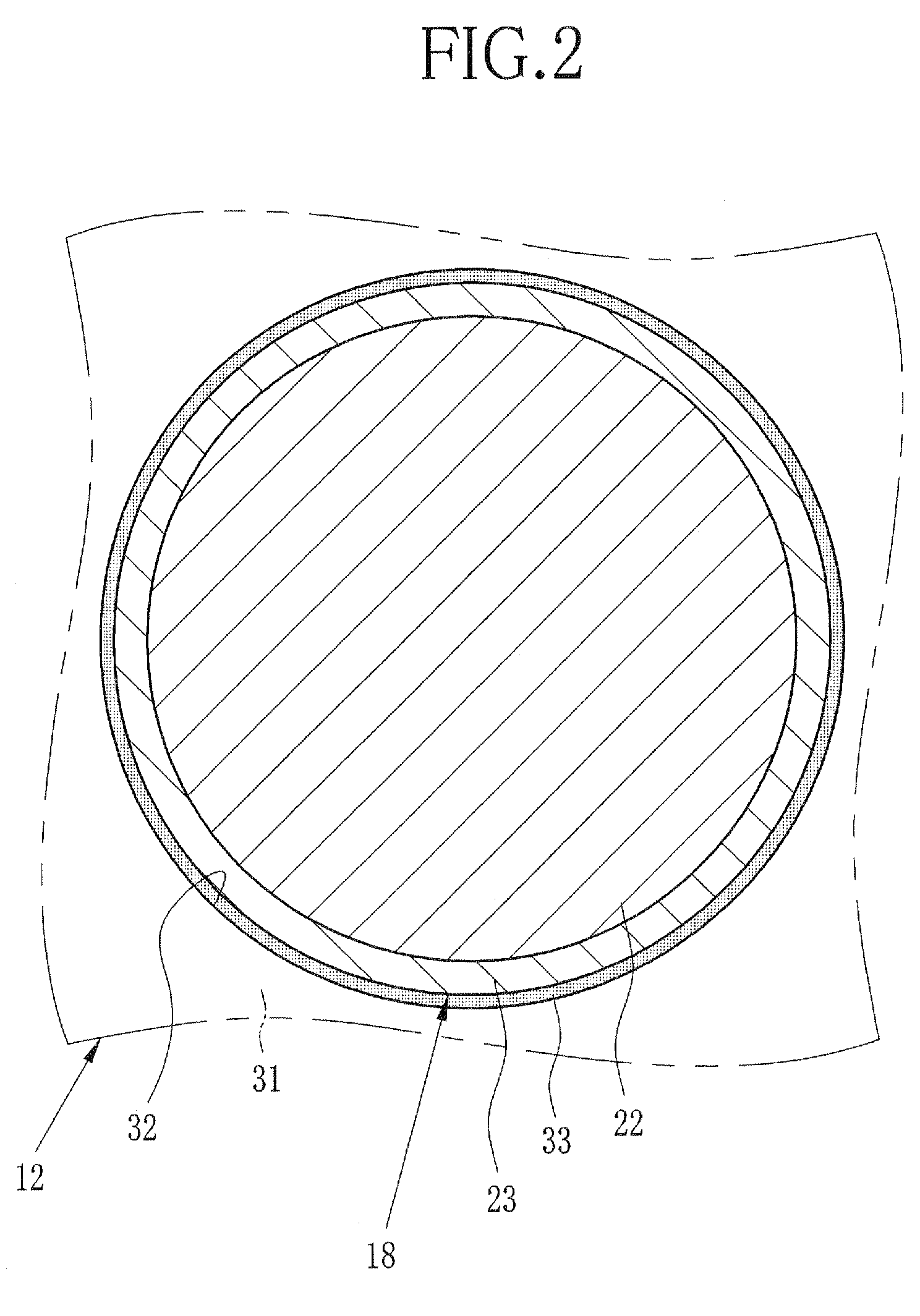
[0043]After the optical fiber 18 was fixed to the single-core ferrule 12, the end surface 31 of the single-core ferrule 12 was polished, according to the above-described polishing method, into a convex surface with the curvature radius R1 of 120 mm. After the optical fiber bundle 19 was fixed to the multi-core ferrule 14, the end surface 49 of the multi-core ferrule 14 was polished into a convex surface with the curvature radius R2 of 25 mm. The polished single-core ferrule 12 and the multi-core ferrule 14 were placed inside the plugs 13 and 15, respectively. These plugs 13 and 15 were attached to the adaptor 17, and thereby completing the connection structure 11. The assembly method of the connection structure was same as described above in the following experiments and comparative experiments, and therefore only the surface processing of the single-co...

example 2

[0058]Hereinafter, Example 2 of the present invention is explained.

Experiment 1

[0059]Based on the results of Example 1, the end surface 31 of the single-core ferrule 12 was finished into a convex surface with the curvature radius R1 of at least 50 mm (R1≧50 mm). The end surface 49 of the multi-core ferrule 14 was finished into a convex surface with the curvature radius R2 of 38.7 mm (R2=38.7 mm).

Experiment 2

[0060]The end surface 31 of the single-core ferrule 12 was finished into a convex surface with the curvature radius R1 of at least 50 mm (R1≧50 mm). The end surface 49 of the multi-core ferrule 14 was finished into a convex surface with the curvature radius R2 of 25 mm (R2=25 mm).

Experiment 3

[0061]The end surface 31 of the single-core ferrule 12 was finished into a convex surface with the curvature radius R1 of at least 50 mm (R1≧50 mm). The end surface 49 of the multi-core ferrule 14 was finished into a convex surface with the curvature radius R2 of 18.3 mm (R2=18.3 mm).

example 3

[0069]Hereinafter, Example 3 of the present invention is explained. A relation between a width of the gap Δ and a shadow was studied.


PUM


Abstract

An optical fiber connection structure includes a single-core plug holding a single-core ferrule, a multi-core plug holding a multi-core ferrule, and an adaptor having a tubular sleeve. The single-core ferrule made of zirconia (ZrO2) has a cylindrical shape and is held in a holder made of stainless steel (SUS). The single-core ferrule has a convex end surface whose curvature radius R1 is at least 50 mm. The multi-core ferrule made of zirconia (ZrO2) has a cylindrical shape and is held in a holder made of stainless steel (SUS). The multi-core ferrule has a convex end surface whose curvature radius R2 is at least 18.3 mm and at most 38.7 mm. When the first and second plugs are attached to the adaptor, the singe-core ferrule and the multi-core ferrule are respectively inserted from the opposite ends into the sleeve, and both of the end surfaces of the ferrules are pressed against each other.

Description

BACKGROUND OF THE INVENTION[0001]1. Field of the Invention[0002]The present invention relates to a connection structure for connecting an optical fiber bundle to a single optical fiber, and also to a multi-core ferrule for holding the optical fiber bundle.[0003]2. Description Related to the Prior Art[0004]Since optical fibers are capable of transmitting a large volume of information, they are widely used as optical waveguides in the communication field and the industrial field. The optical fibers are formed of, for example, a core having a diameter of 205 μm and a clad surrounding the core and having an outer diameter of 250 μm. The outside of the clad is usually protected with a coating material.[0005]When the optical fibers are connected, a ferrule is attached to an end of each optical fiber so that their axes are aligned parallel to each other. The ferrule has a cylindrical shape and has a through hole extending in its axial direction. The optical fiber is inserted into this thro...

Claims


Application Information

Patent Timeline
Patent Type & Authority Patents(United States)
IPC IPC(8): G02B6/32
CPCG02B6/3825G02B6/403G02B6/3821
Inventor IMADA, YUUKISHIMOTU, SHINICHI
Owner ADTEC ENG
Why Eureka
Try Eureka