Contaminant-deflector labyrinth seal and method of operation

a labyrinth seal and contaminant technology, applied in the direction of machines/engines, mechanical equipment, liquid fuel engines, etc., can solve the problems of loss of power, difficulty in preventing leakage or loss of pressure or vacuum, etc., and achieve the effect of preventing contamination

Active Publication Date: 2012-05-15
HONEYWELL INT INC
View PDF18 Cites 16 Cited by
  • Summary
  • Abstract
  • Description
  • Claims
  • Application Information

AI Technical Summary

Benefits of technology

[0017]In another aspect of the invention, a method of preventing contamination between an upstream space and a downstream space containing fluids at different pressures comprises allowing a portion of the fluid flowing in the upstream space to flow through the seal assembly as stated above; venting the contaminated fluid flowing through the seal assembly via the at least one vent hole to prevent the contaminated fluid from reaching the contamination-sensitive components downstream.

Problems solved by technology

In such systems, it is continuously a problem to seal an opening through which a rotatable shaft protrudes.
The problem is manifested in the difficulty of preventing leakage or loss of pressure or loss of vacuum while at the same time avoiding undue shaft friction.
The shaft friction can generate heat, cause loss of power, and damage the machinery.
Air cycle machines that operate in dusty environments prematurely fail due to sand or dust entering the air bearing cooling circuit causing bearing wear, erosion and failure.
At startup, an air cycle machine is not yet fully pressurized, and when a labyrinth seal that has one inner diameter is used to seal the opening through which a rotatable shaft protrudes, contaminated air flowing through the labyrinth seal flows directly into the adjacent journal bearings.
Furthermore, sand and dust particles deposited between the bearings and the shaft abrade the bearings when the shaft starts to move against the stationary bearings.
When the air cycle machine starts, contaminated air that leaks through the labyrinth seal may deposit contaminants in the adjacent journal bearings.

Method used


Image

  • Contaminant-deflector labyrinth seal and method of operation
  • Contaminant-deflector labyrinth seal and method of operation
  • Contaminant-deflector labyrinth seal and method of operation

Examples


Embodiment Construction

[0027]The following detailed description is of the best currently contemplated modes of carrying out the invention. The description is not to be taken in a limiting sense, but is made merely for the purpose of illustrating the general principles of the invention, since the scope of the invention is best defined by the appended claims. Like reference numerals refer to like elements in the drawings.

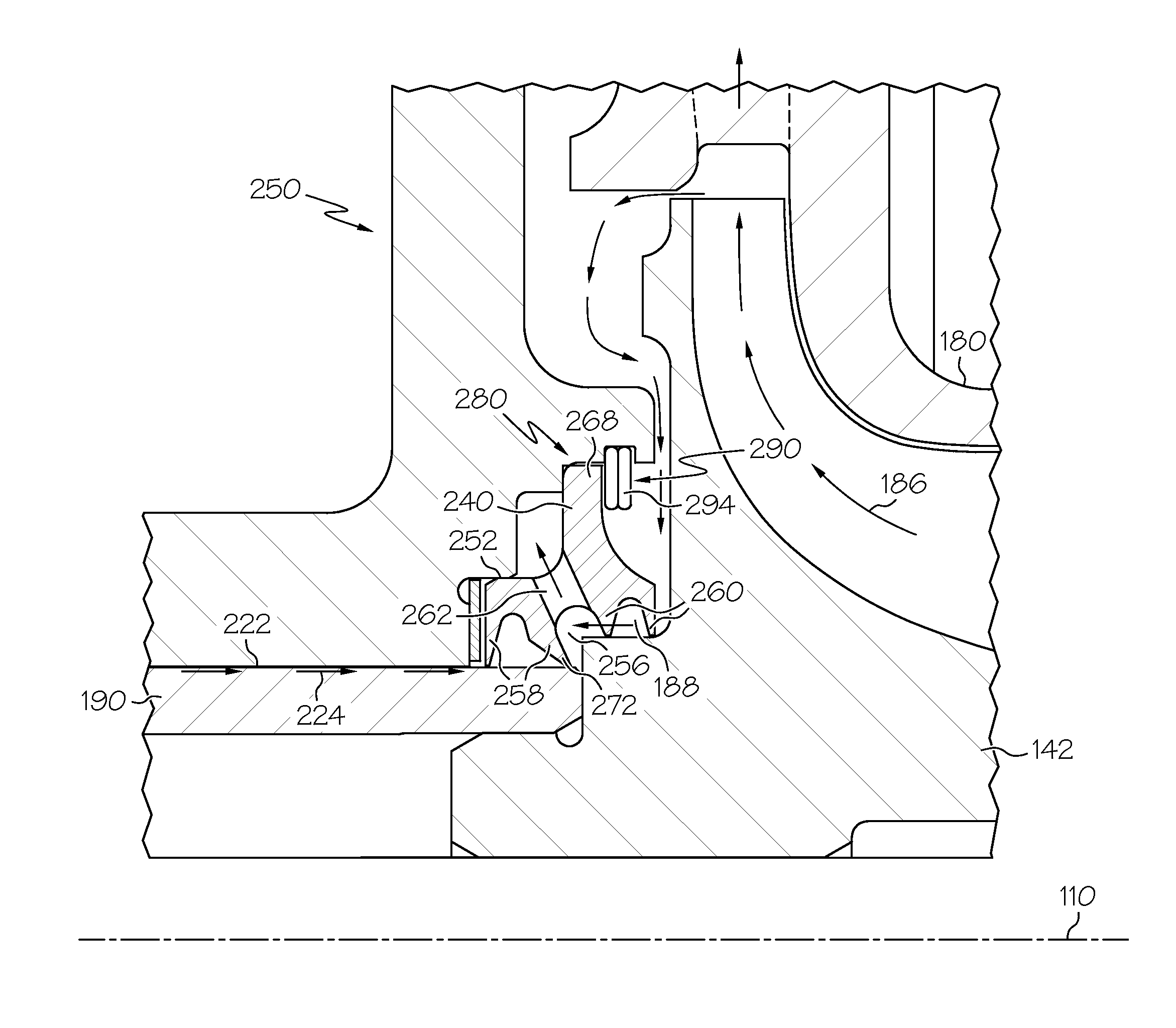
[0028]Embodiments of the present invention can be used to separate a fluid in a higher pressure higher temperature upstream space from a fluid in a lower pressure lower temperature downstream space. In particular, the invention may be used as a filtering labyrinth seal assembly for a refrigeration pack in an aviation turbojet, where the fluid in the upstream space and downstream space are both air; for an underwater vehicle, where the fluid in the upstream space and the fluid in the downstream space are both water; and for a ground based compressor in which the fluid in the upstream space a...


PUM


Abstract

A seal assembly for deflecting contaminated fluid flowing through the seal assembly from an upstream space to a downstream space includes an annular housing, at least one vent hole peripherally disposed on the annular housing, a first set of seals disposed within the annular housing adjacent to the downstream space, the first set of seals having an inclined surface to deflect the flow of contaminated fluid through the at least one vent hole, and a second set of seals mounted on the shaft, disposed within the annular housing, adjacent to the first set of seals and adjacent to the upstream space. The second set of seals may have larger inside diameter than the first set of seals. The seal assembly may prevent contaminated fluid from entering an air bearing cooling circuit, thereby preventing bearing wear, erosion and failure.

Description

GOVERNMENT RIGHTS[0001]This invention was made with Government support under the N00019-96-C-0054 contract awarded by the US Navy. The Government has certain rights in this invention.BACKGROUND OF THE INVENTION[0002]The present invention relates generally to contaminant-blocking or deflecting labyrinth seals and, more particularly, to labyrinth seals that separate two spaces containing fluids at different pressures, such as, for example, a seal placed between a shaft and compression chamber housing of a gas turbine or of an aviation turbojet.[0003]Environmental control systems for aircraft typically employ air cycle machines and heat exchangers to cool and condition high-pressure air supplied by either the engines or an auxiliary power unit. In these systems, a compressed air supply air is further compressed in a compressor, cooled in a heat exchanger, and expanded in a turbine. The turbine outlet air, cooled by expansion, flows into the aircraft. Since the aircraft air is maintaine...

Claims


Application Information

Patent Timeline
Patent Type & Authority Patents(United States)
IPC IPC(8): F04D27/02
CPCF01D11/02F01D11/04F04D29/104F16J15/447F05D2220/40
Inventor JOCO, FIDEL MANALOSAVILLE, MARSHALLKANG, ALAN
Owner HONEYWELL INT INC
Why Eureka
Try Eureka