Imaging apparatus for electronic endoscope and electronic endoscope

a technology of electronic endoscope and imaging apparatus, which is applied in the field of imaging apparatus, can solve the problems of increasing part cost, increasing part cost, and large thickness of the entire thickness, and achieves the effects of low cost, reduced thickness from imaging device to cover glass, and narrowing of the insertion section of electronic endoscop

Inactive Publication Date: 2012-05-15
FUJIFILM CORP
View PDF12 Cites 12 Cited by
  • Summary
  • Abstract
  • Description
  • Claims
  • Application Information

AI Technical Summary

Benefits of technology

[0017]The imaging apparatus for the electronic endoscope of the present invention uses the bare chip for the imaging device, and the circuit board having approximately the same thickness as the bare chip is attached to the imaging device. The bare chip and the circuit board are connected electrically to each other through the signal terminals, which are arranged near the edges on their surface, so that the thickness from the imaging device to the cover glass can be reduced extremely. Thereby, the diameter of the insertion section of the electronic endoscope can be narrowed. In addition, the imaging apparatus for the electronic endoscope is constituted of parts without requiring complicate processing, so that it can be produced at low cost.
[0018]Moreover, since the conducting plate is bridged over the rear surfaces of the imaging device and the circuit board, the adhesive attachment of the imaging device to the circuit board is mechanically enhanced. Further, driving heat of the imaging device can be dissipated efficiently.
[0019]According to the electronic endoscope of the present invention, since the forceps channel is arranged such that the outer circumference fits into the cut portion, which is formed in the rear surfaces of the imaging device and the circuit board by the conducting plate, it is possible to reduce the dimension in a direction that the imaging apparatus and the forceps channel are lined, so that the insertion section of the electronic endoscope can be narrowed moreover.

Problems solved by technology

However, since the CCD is placed on the board in the Patent Nos. 2853939 and 3186965, the entire thickness becomes large.
Therefore, there is a problem that the part cost is increased in both the cases.
However, since the opening hole for arranging the CCD on the circuit board is required, there is also a problem that the part cost is increased.
In the Japanese Patent Laid-Open Publication No. 2001-128937, although the diameter of the insertion section is narrowed by dividing the signal cables, since the imaging device and the forceps channel which occupy the most of the area in the insertion section are not considered, the problem is not solved fundamentally.

Method used


Image

  • Imaging apparatus for electronic endoscope and electronic endoscope
  • Imaging apparatus for electronic endoscope and electronic endoscope
  • Imaging apparatus for electronic endoscope and electronic endoscope

Examples


Embodiment Construction

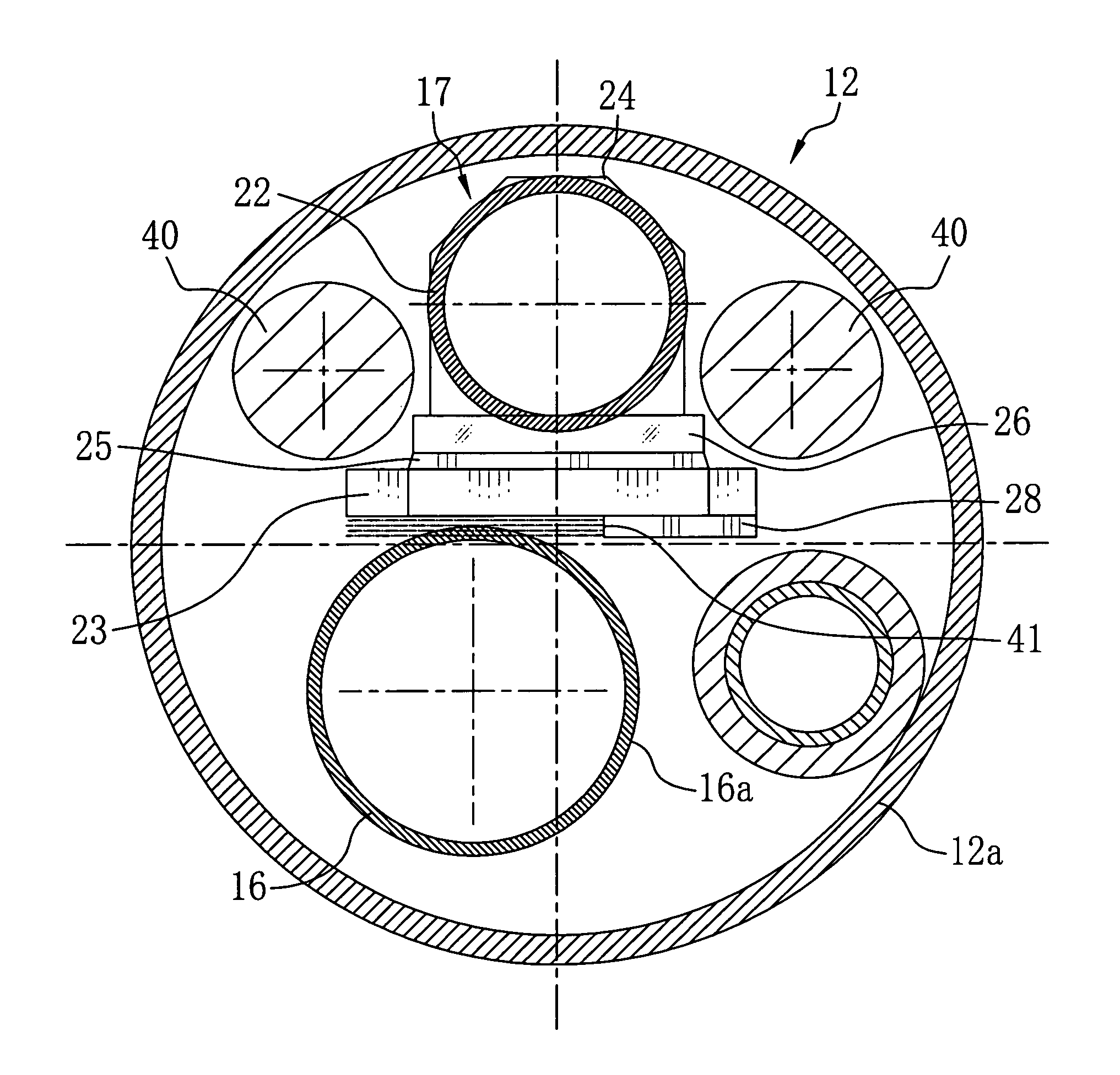
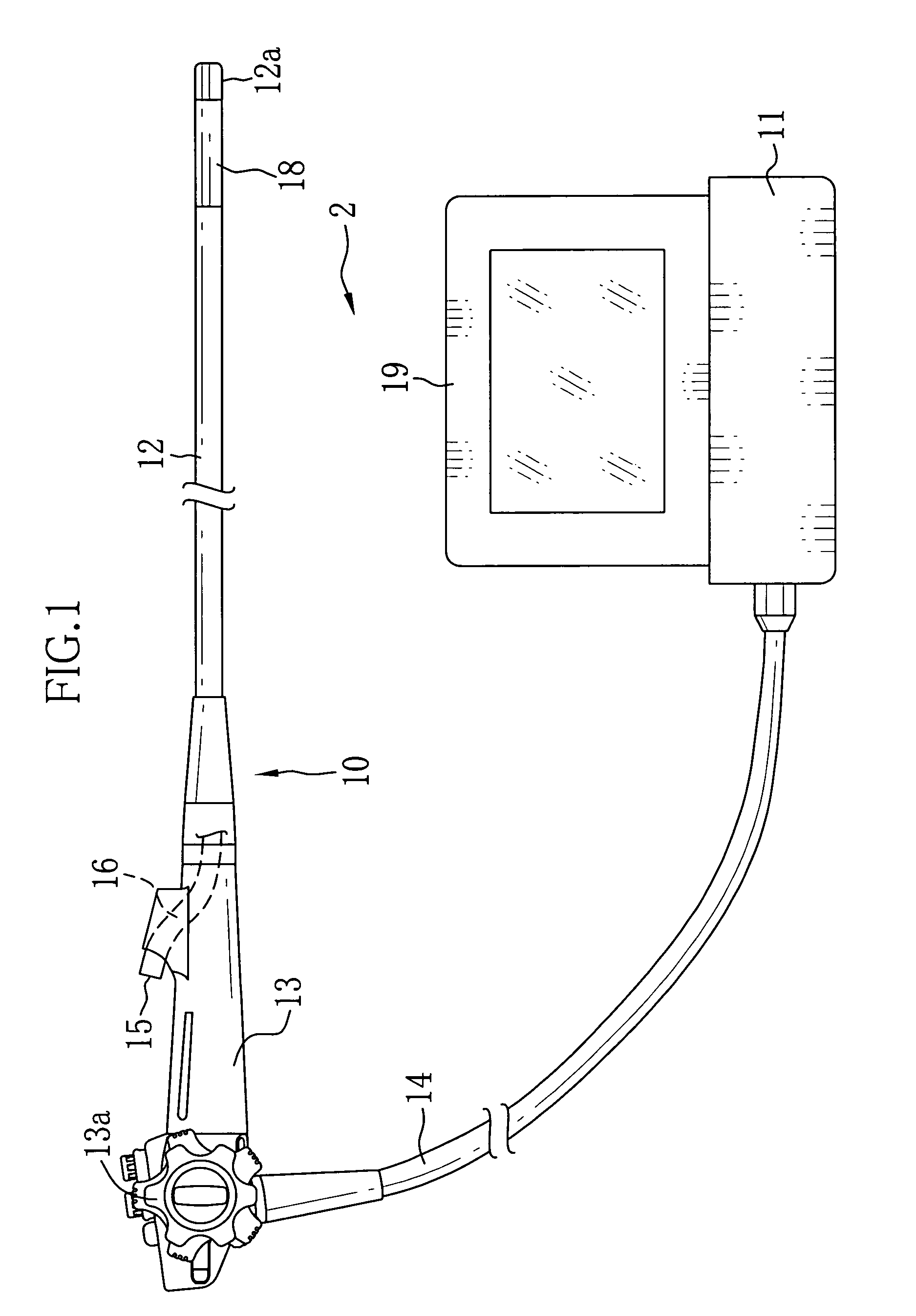
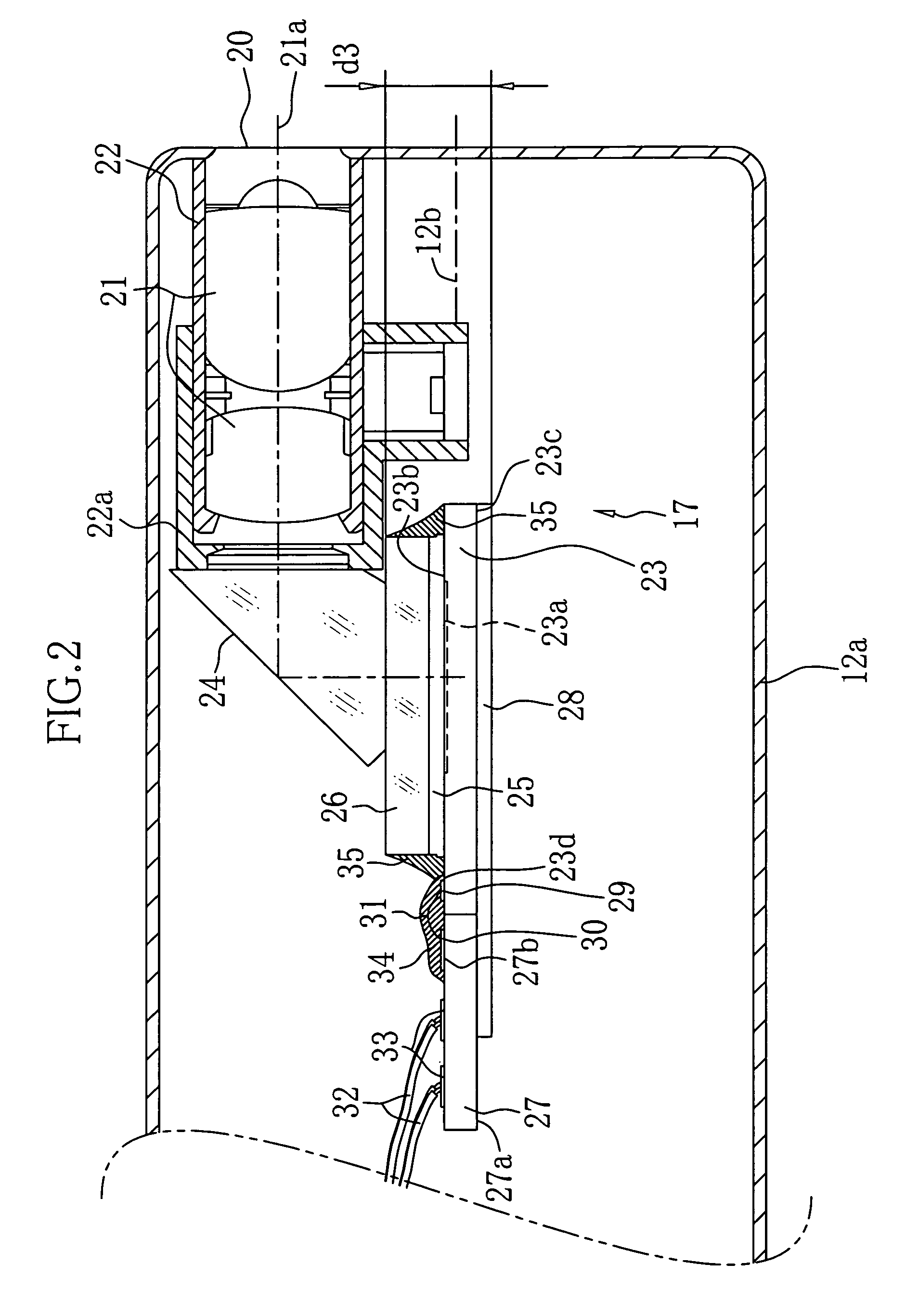
[0025]In FIG. 1, an electronic endoscope apparatus 2 is constituted of an electronic endoscope 10, a processor device 11, a light source device (not shown) and so forth. The electronic endoscope 10 is provided with an insertion section 12 to be inserted into a body cavity, an operating section 13 connected to a base end portion of the insertion section 12, and a cord 14 for the connection to the processor device 11 and the light source device. The operating section 13 is provided with a forceps opening 15 into which a treatment tool is inserted. The forceps opening 15 is connected to a forceps channel 16 provided in the insertion section 12 as shown by dashed lines. An imaging apparatus 17 (see FIG. 2) for imaging the inside of the body cavity is built in a front end portion 12a provided over the front end of the insertion section 12.

[0026]A curving portion 18 to which plural curving pieces are connected is provided behind the front end portion 12a. A wire provided in the insertion ...


PUM


Abstract

An imaging apparatus for an electronic endoscope includes a bare chip of CCD, a circuit board with approximately the same thickness as the bare chip, and a conducting plate with no less than 1 / 4 width of the bare chip. The bare chip has terminals on the surface with an imaging surface. The terminals are arranged near the edge facing the rear end of an insertion section of the electronic endoscope. The circuit board has terminals on the surface near the edge facing the front end of the insertion section. These terminals are connected by wire bonding. The conducting plate is attached along one side of the rear surface of the CCD and the circuit board for electrical connection. A forceps channel is provided such that its outer circumference fits partially into a cut portion formed on the rear surfaces of the CCD and the circuit board by the conducting plate.

Description

BACKGROUND OF THE INVENTION[0001]1. Field of the Invention[0002]The present invention relates to an imaging apparatus for an electronic endoscope for imaging an object in a body cavity, and an electronic endoscope having the imaging apparatus built-in.[0003]2. Description of the Related Arts[0004]Medical diagnoses using an electronic endoscope are widely performed. An imaging apparatus with an imaging device such as a CCD is built in a front end of an insertion section of the electronic endoscope, which is inserted into a body cavity. A processor device applies signal processing to an imaging signal obtained with the CCD, and an image in the body cavity can be observed on a monitor. Since a forceps channel through which a treatment tool is inserted is provided in the insertion section, biopsy in which affected tissue is removed with the treatment tool can be performed with observing the image in the body cavity.[0005]As the imaging apparatus for the electronic endoscope, there is a ...

Claims


Application Information

Patent Timeline
Patent Type & Authority Patents(United States)
IPC IPC(8): A61B1/005
CPCA61B1/05A61B1/051H04N5/2252A61B1/042H04N2005/2255H04N23/555H04N23/51
Inventor MINAMI, ITSUJITAKAHASHI, KAZUAKI
Owner FUJIFILM CORP
Why Eureka
Try Eureka