
Wireless communication method and wireless communication system

a wireless communication and wireless communication technology, applied in the field of wireless communication methods and systems, can solve the problem and achieve the effect of reducing the power consumption of each wireless node, reducing unnecessary radio wave radiation, and reducing the transmission power of the least possible transmission power for time synchronization

Active Publication Date: 2012-05-15
NEC CORP
View PDF12 Cites 0 Cited by
  • Summary
  • Abstract
  • Description
  • Claims
  • Application Information

AI Technical Summary

Benefits of technology

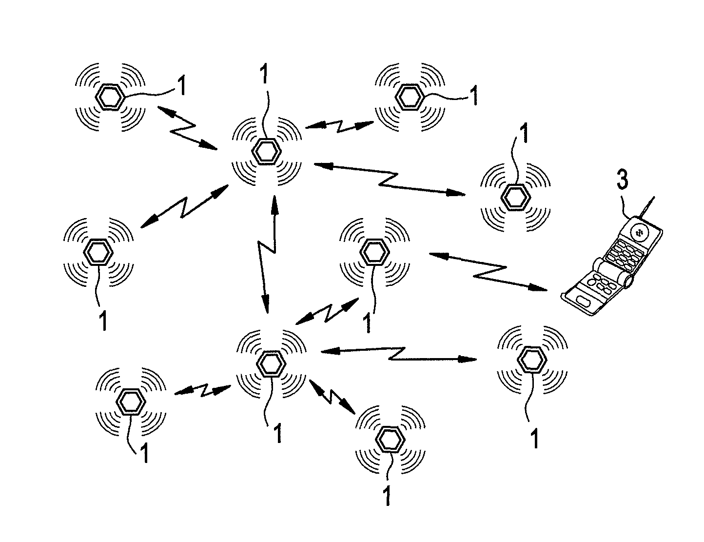
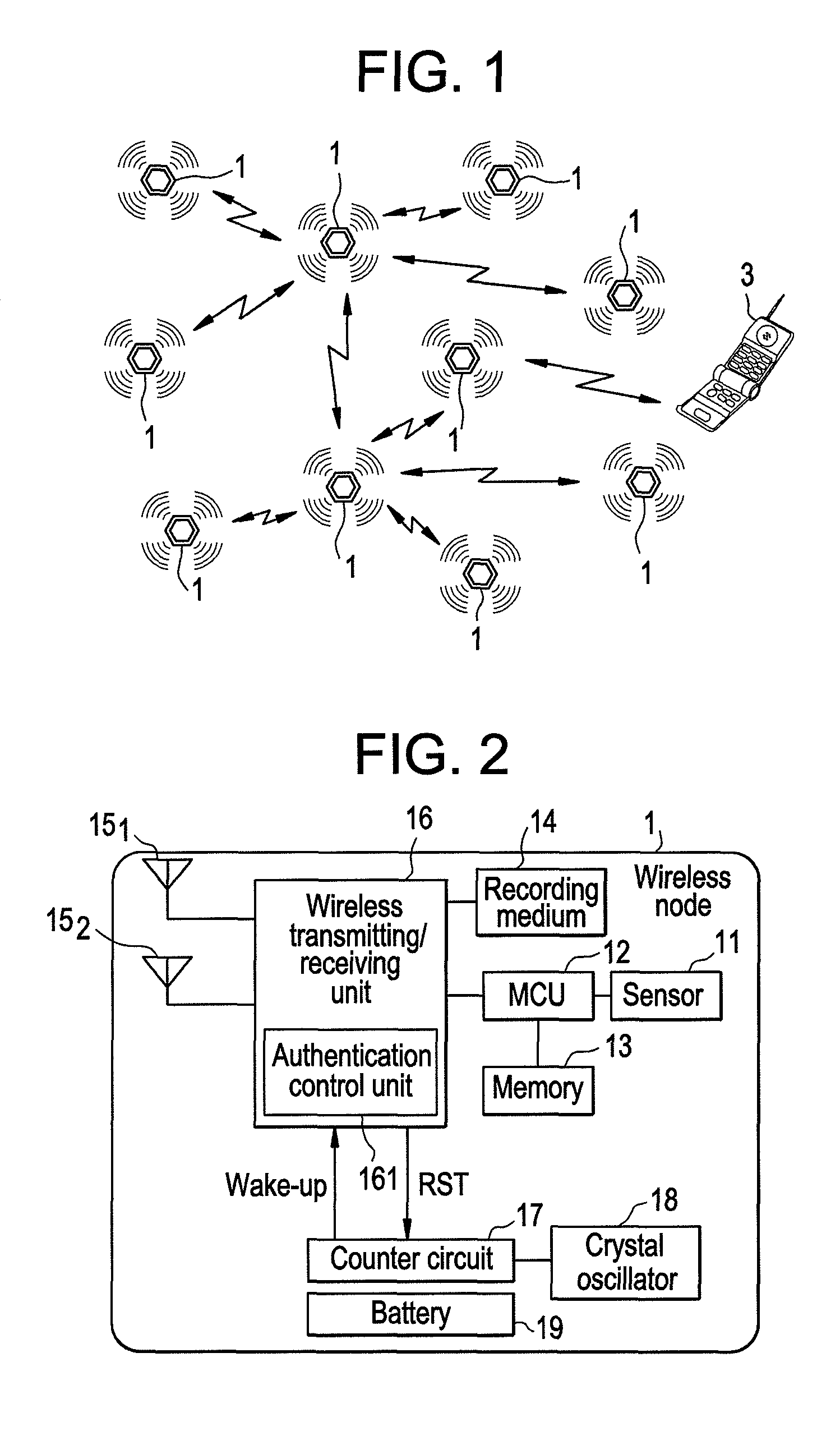
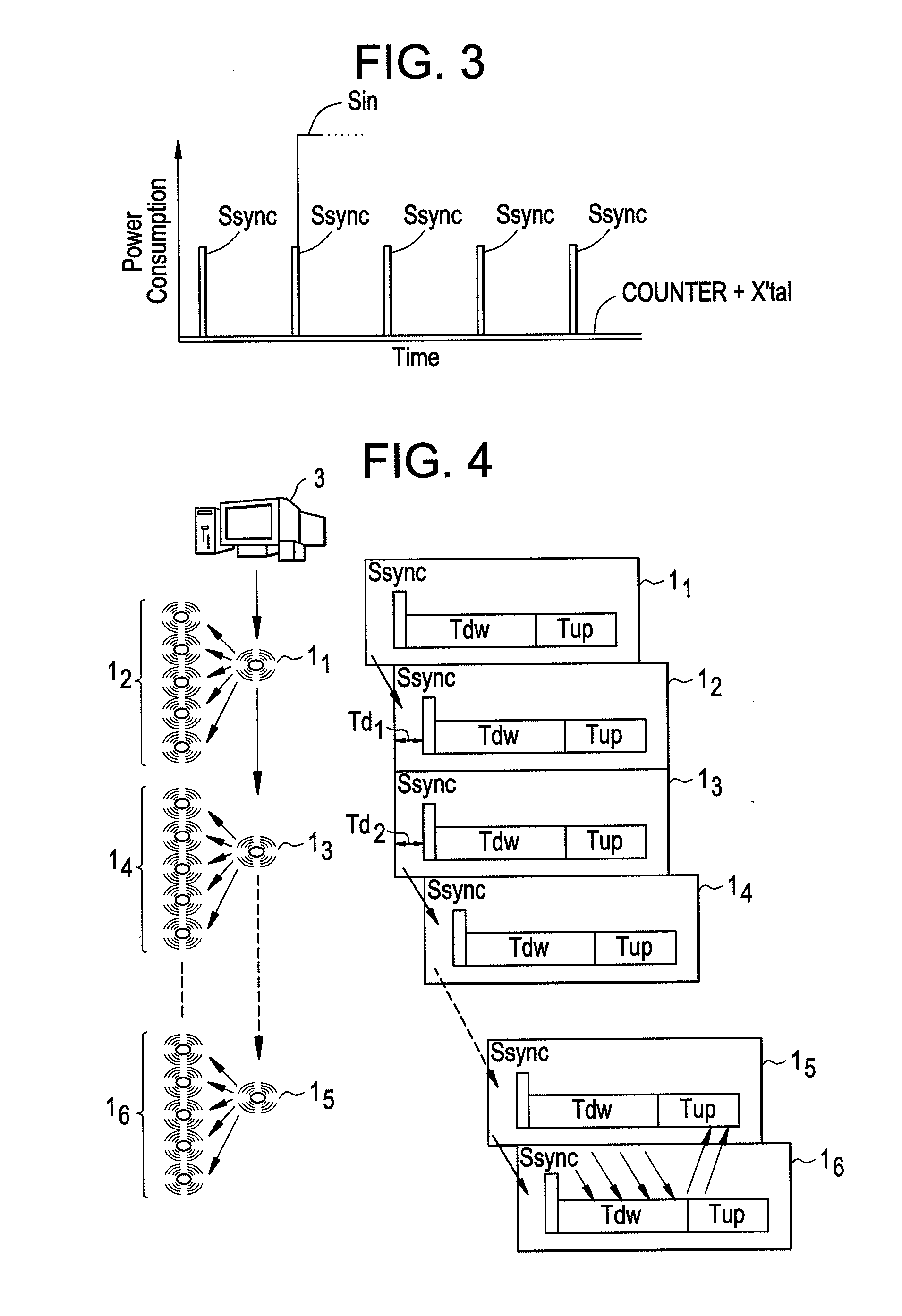
The present invention provides a wireless communication method and system that saves power and is less expensive. This is achieved by transmitting a time synchronizing signal to each wireless node by multihop to synchronize time among a plurality of wireless nodes. Each wireless node only has to transmit a time synchronizing signal in each predetermined period, and only consumes the least possible transmission power for time synchronization. This reduces unnecessary radio wave radiation and maintains the signal-to-noise ratio (S / N ratio) of the entire wireless communication system at a high value. Additionally, a maintenance-free operation can be realized for several years using a small and low cost battery.

Problems solved by technology

With the above-mentioned configuration, each wireless node only has to transmit a time synchronizing signal in each predetermined period to an adjacent wireless node, and only consumes the least possible transmission power for time synchronization.

Method used


Image

  • Wireless communication method and wireless communication system
  • Wireless communication method and wireless communication system
  • Wireless communication method and wireless communication system

Examples


first exemplary embodiment

[0044]FIG. 5 shows a first exemplary embodiment of the wireless communication system of the present invention, and is a block diagram of the configuration of the wireless transmitting / receiving unit of a wireless node.

[0045]As shown in FIG. 5, according to the present exemplary embodiment, wireless transmitting / receiving unit 16 is provided with two units, that is, first transmitting / receiving unit 162 and second transmitting / receiving unit 163 corresponding to two types of carrier frequency.

[0046]As described above, in the present invention, the communication speed in the up link period Tup is set higher than the communication speed in the down link period Tdw. Therefore, in the present exemplary embodiment, first transmitting / receiving unit 162 corresponding to a-relatively low carrier wave (for example, 400 MHz band) is used for communications of the down link period Tdw. In addition, second transmitting / receiving unit 163 corresponding to a relatively high carrier wave (for exam...

second exemplary embodiment

[0054]FIG. 7 is a block diagram of the configuration of the second exemplary embodiment of the wireless communication system of the present invention.

[0055]The wireless communication system shown in FIG. 7 shows an example of a ubiquitous sensor network having a plurality of wireless nodes provided with monitor camera 4 as a sensor.

[0056]The wireless communication system shown in FIG. 7 is an example of transmitting a transfer instruction of a video signal taken by monitor camera 4 to predetermined wireless node 1 by server device 3, and is an example of transferring to server device 3 a video signal from wireless node 1 specified by server device 3 through a plurality of wireless nodes.

[0057]An instruction to transfer a video signal is several byte information, and a video signal is data of several tens to several hundreds of Kbytes. Therefore, the wireless communication system shown in FIG. 7 performs, for example, low speed communications of 2.4 kbps in the down link period Tdw, ...


PUM


Abstract

A time synchronizing signal for synchronizing the times of wireless nodes capable of wireless communication is transmitted to the wireless nodes by multihop. Optional information is transferred by multihop from a predetermined wireless node to an optional node along the same path as the transfer path of the time synchronizing signal by the wireless nodes. Information to respond the optional information is transferred by multihop from the optional wireless node to the predetermined wireless node along the reverse path to the transfer path of the time synchronizing signal.

Description

TECHNICAL FIELD[0001]The present invention relates to a wireless communication method and system preferably applicable to a ubiquitous sensor network.BACKGROUND ART[0002]With the recent progress of semiconductor microelectronics, a large number of less expensive wireless communication devices have been constantly provided, and equipment for wireless communications has been widely used in daily life. The era is approaching in which it will be common for all equipment to be installed with wireless communication devices. The wireless communication device in the era is expected to perform a long time operation using a battery so that it can be used in a place where an infrastructure does not exist, that is, where power cannot be easily supplied. Therefore, a power-saving technique for a wireless communication device is an essential requirement.[0003]A network referred to as a ubiquitous sensor network is intended not only to connect equipments in human's activity area such as various ty...

Claims


Application Information

Patent Timeline
Patent Type & Authority Patents(United States)
IPC IPC(8): H04J3/06H04W56/00
CPCH04B7/2696H04W56/002
Inventor KIMURA, TOHRU
Owner NEC CORP
Learn More