Wireless power and communication system

a technology of communication system and power supply, applied in the direction of receiver monitoring, near-field system using receivers, transportation and packaging, etc., can solve the problem that the power supply itself cannot be performed, and achieve the effect of improving power supply efficiency

Active Publication Date: 2012-05-15
SONY CORP
View PDF21 Cites 293 Cited by
  • Summary
  • Abstract
  • Description
  • Claims
  • Application Information

AI Technical Summary

Problems solved by technology

Further, when the power receiving apparatus is located outside a power supplyable range from a power transmitting apparatus, power supply itself may not be able to be performed.

Method used


Image

  • Wireless power and communication system
  • Wireless power and communication system
  • Wireless power and communication system

Examples


first embodiment

[1] First Embodiment

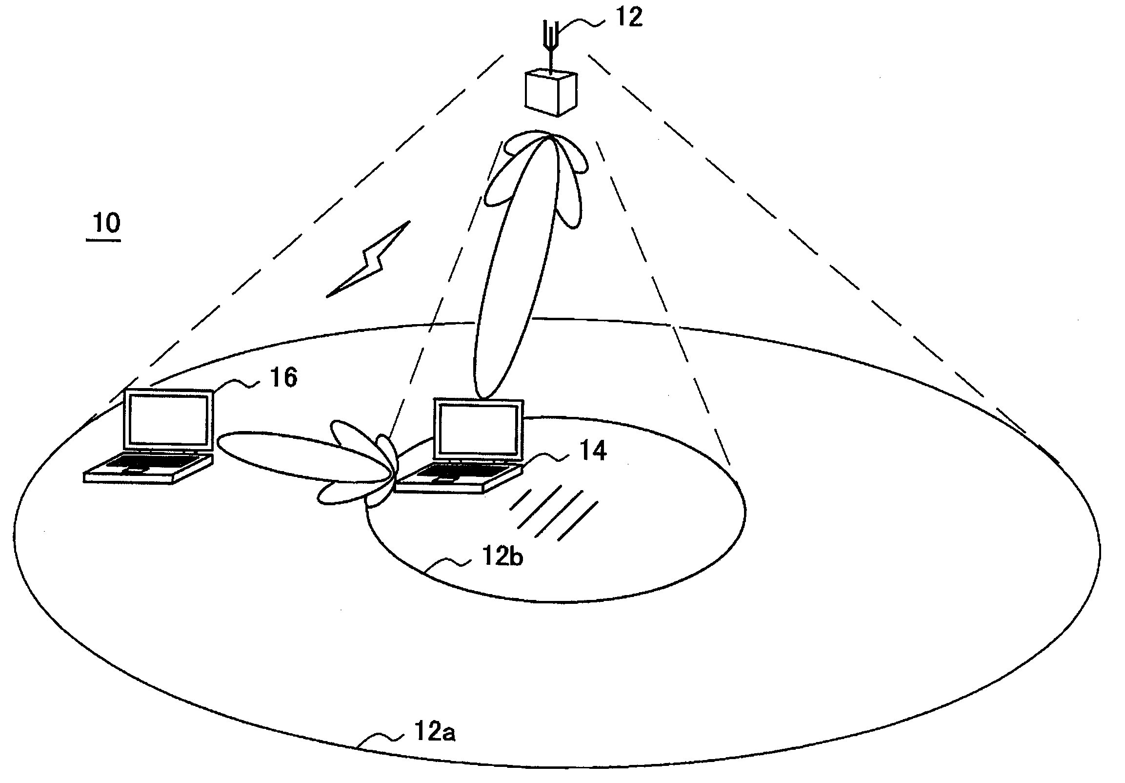
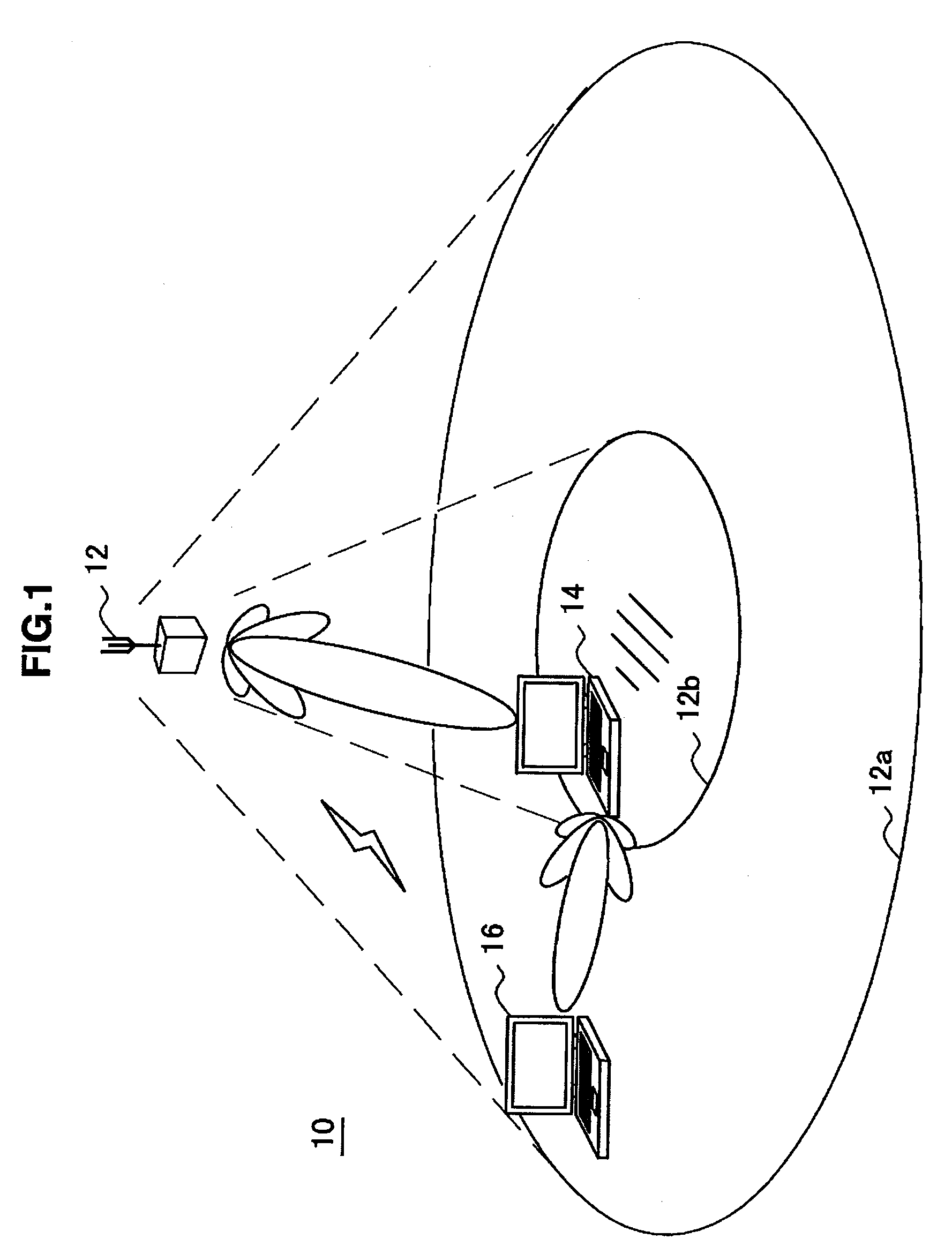
[0047]First, FIG. 1 is an explanatory diagram showing a configuration of a wireless communication system 10 according to a first embodiment of the present invention. The wireless communication system 10 shown in FIG. 1 includes a first wireless communication apparatus 12, a second wireless communication apparatus 14, and a power receiver apparatus 16.

[0048]Although in FIG. 1 a wireless access point is shown as the first wireless communication apparatus 12, the first wireless communication apparatus 12 is not limited to a wireless access point. The first wireless communication apparatus 12 may be, for example, a network apparatus such as a router having a wireless communication function, a data processing apparatus such as a PC (Personal Computer) or workstation, or a household appliance such as a music / video player or phone.

[0049]Further, although in FIG. 1 PCs are shown as the second wireless communication apparatus 14 and the power receiver apparatus 16, the se...

second embodiment

[2] Second Embodiment

[0152]FIG. 15 is an explanatory diagram showing a configuration of a wireless communication system 20 according to the second embodiment of the present invention. The wireless communication system 20 shown in FIG. 15 includes a first wireless communication apparatus 12, a second wireless communication apparatus 24, and a power receiver apparatus 16.

[0153]Although in FIG. 15 a wireless access point is shown as the second wireless communication apparatus 24, the second wireless communication apparatus 24 is not limited to a wireless access point. The second wireless communication apparatus 24 may be, for example, a network apparatus, a data processing apparatus, or a household appliance which is exemplified in connection with the first wireless communication apparatus 12 in the description of FIG. 1.

[0154]Referring to FIG. 15, in addition to an area 12b around the first wireless communication apparatus 12, an area 24b is shown around the second wireless communicat...


PUM


Abstract

The present invention provides a wireless communication apparatus including: a communication processing unit that transmits and receives a radio signal; a wireless power transmitting unit that supplies power wirelessly to an apparatus located within a power supplyable range; a location data obtaining unit that obtains location data of a power receiver apparatus; and a control unit that controls a power supply to the power receiver apparatus based on the location data of the power receiver apparatus obtained by the location data obtaining unit.

Description

BACKGROUND OF THE INVENTION[0001]1. Field of the Invention[0002]The present invention relates to a wireless communication apparatus, a method for supplying power, a program, and a wireless communication system.[0003]2. Description of the Related Art[0004]In the past, wireless power supply techniques have been developed that enable power supply without a physical connection or contact between apparatuses. For supplying power wirelessly, there is a method that performs wireless power supply through, for example, an electromagnetic wave such as a microwave, ultrasound, a resonant magnetic field or electric field, or laser light.[0005]In such wireless power supply techniques, since generally power loss occurs in space, when the distance between a power transmitting apparatus and a power receiving apparatus increases, efficiency of power supply decreases. Further, when the power transmitting apparatus and the power receiving apparatus are separated from each other by a certain distance o...

Claims


Application Information

Patent Timeline
Patent Type & Authority Patents(United States)
IPC IPC(8): H04B5/00
CPCH04B5/0037H04B5/02H02J17/00H02J5/005H04B17/27H02J50/12H02J50/20H02J50/90H02J50/80
Inventor YAMASUGE, HIROYUKI
Owner SONY CORP
Why Eureka
Try Eureka