
Acoustic coating for an aircraft incorporating a frost treatment system by joule effect

a technology of acoustic coating and acoustic treatment, which is applied in the direction of machines/engines, air-flow influencers, instruments, etc., can solve the problems of incompatibility with the coating of acoustic treatment, the system type is not satisfactory, and the frost treatment system cannot function again, so as to reduce the maintenance time and the down time on the ground

Active Publication Date: 2012-05-22
AIRBUS OPERATIONS (SAS)
View PDF9 Cites 26 Cited by
  • Summary
  • Abstract
  • Description
  • Claims
  • Application Information

AI Technical Summary

Benefits of technology

[0017]The object of this invention is to remedy the drawbacks of the prior art by proposing an acoustic coating for an aircraft incorporating a frost treatment system that makes it possible to optimize the operation of each of the treatments.
[0019]This arrangement makes it possible to make the acoustic and frost treatments compatible.
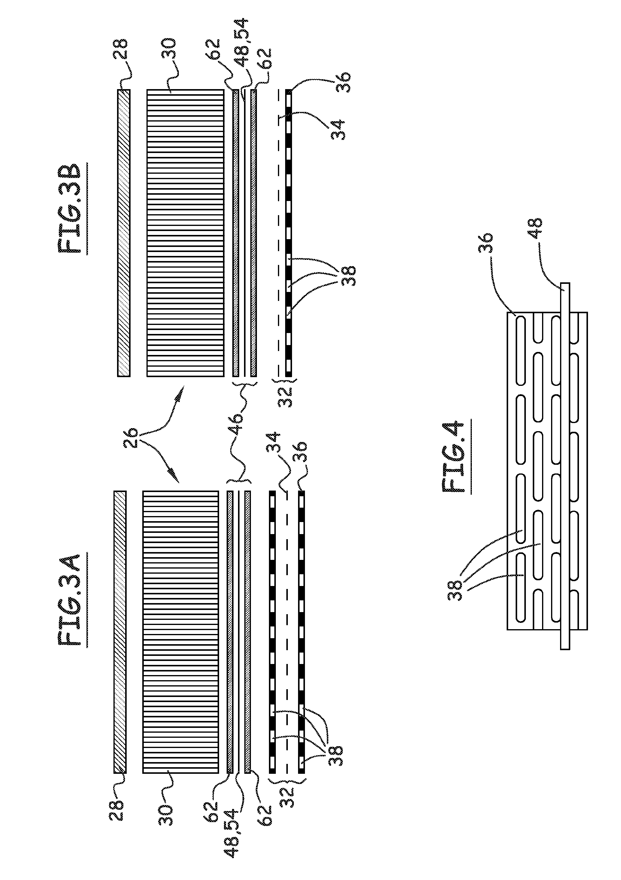
[0020]Preferably, the acoustically resistive structure comprises a structural layer that comprises open zones, and the heating layer is arranged under said structural layer. According to this configuration, the frost treatment system is protected, which makes it possible to reduce the maintenance time and the down time on the ground of the aircraft.

Problems solved by technology

This type of system is not satisfactory because it is relatively fragile and susceptible to being damaged by bird strikes, hail or accidents during maintenance.
In the damaged zones, the frost treatment system can no longer function, making possible the formation and the accumulation of ice or frost.
Finally, it is not compatible with the coatings for the acoustic treatment because its presence on the surface generally changes the performance levels of the acoustic treatment.

Method used


Image

  • Acoustic coating for an aircraft incorporating a frost treatment system by joule effect
  • Acoustic coating for an aircraft incorporating a frost treatment system by joule effect
  • Acoustic coating for an aircraft incorporating a frost treatment system by joule effect

Examples


Embodiment Construction

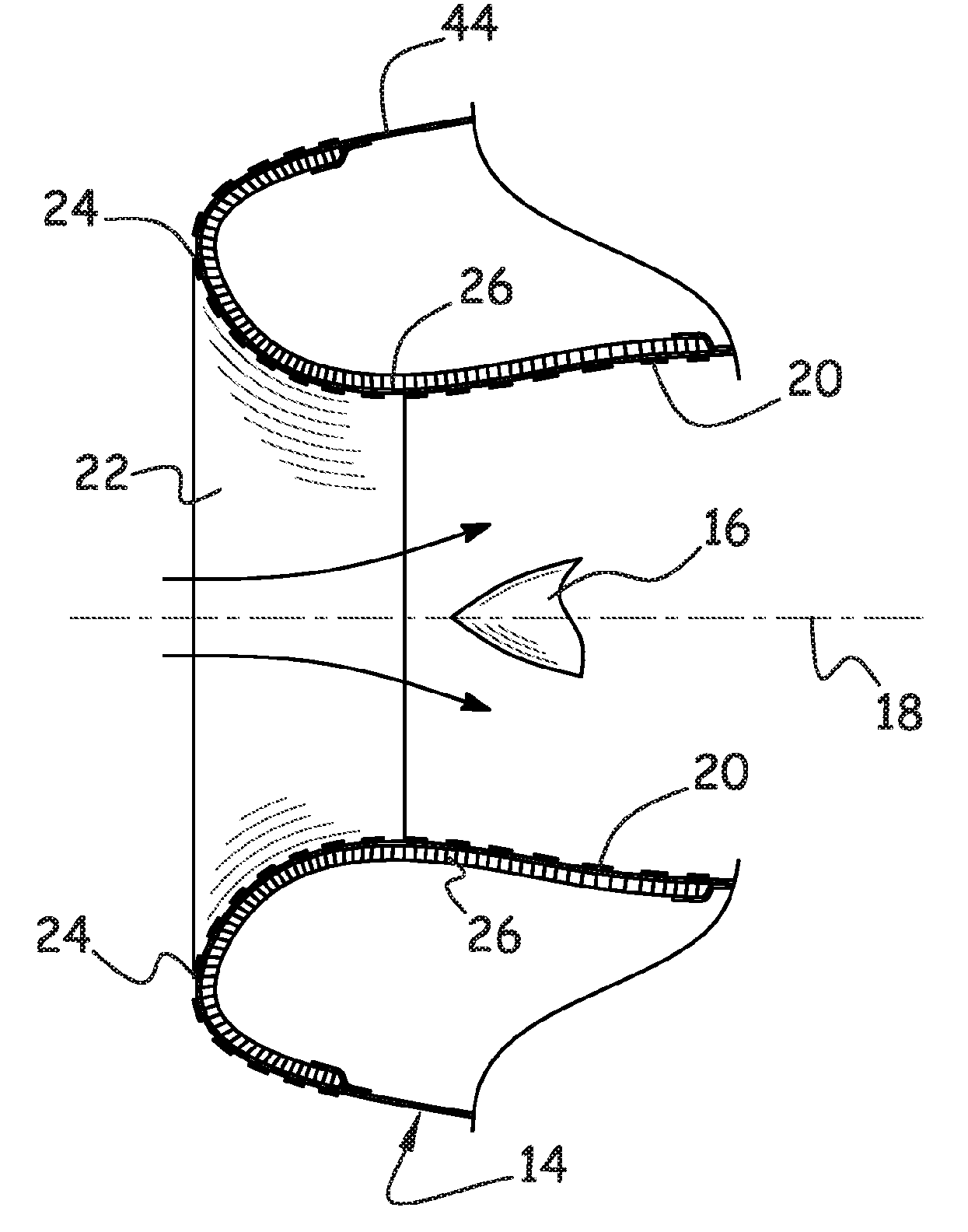
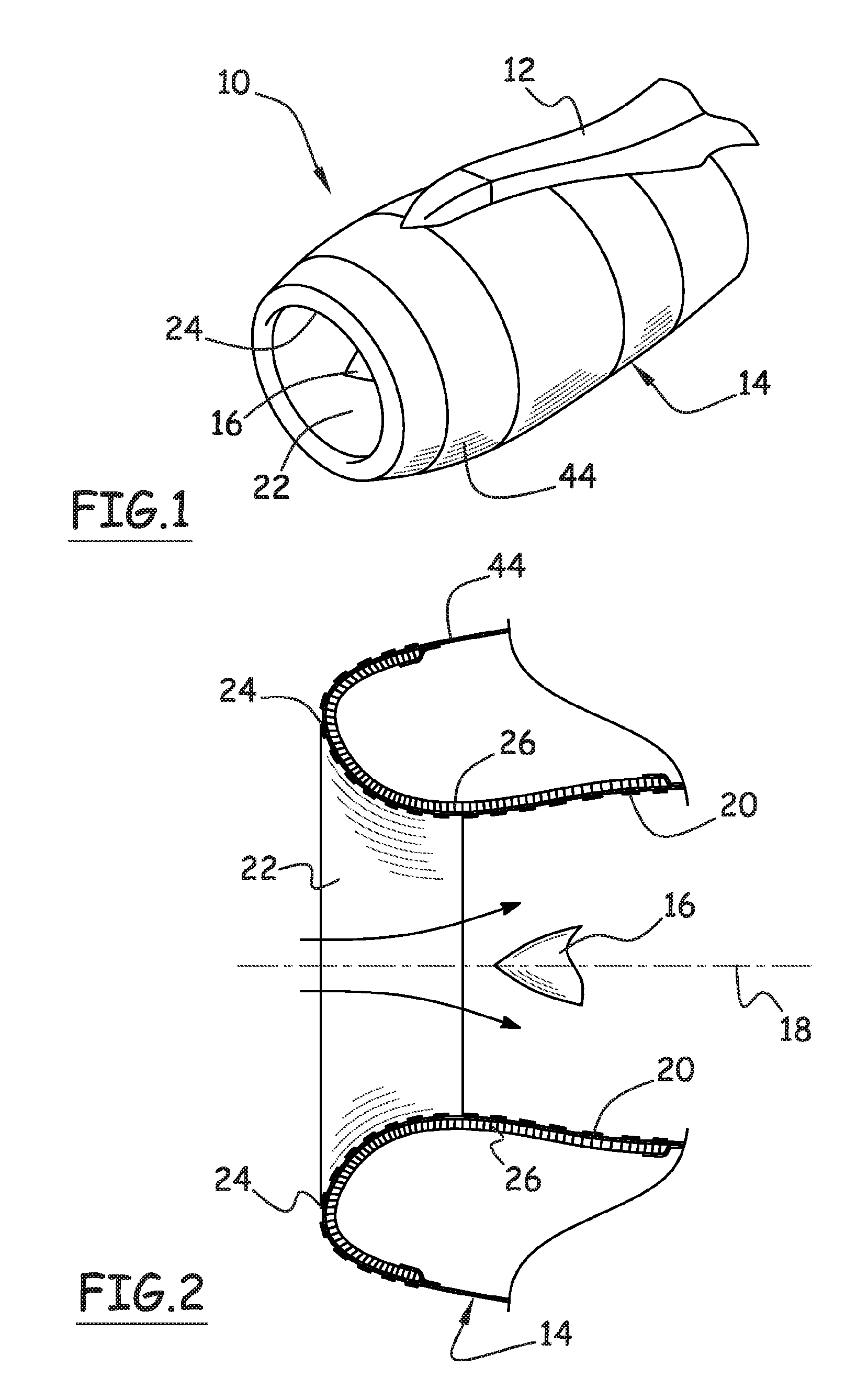
[0044]This invention is now described applied to an air intake of a propulsion unit of an aircraft. However, it can apply to various leading edges of an aircraft or to various surfaces of an aircraft where an acoustic treatment and a frost treatment are performed.

[0045]Hereinafter, frost is defined both as frost and ice, of all kinds, all structures and all thicknesses.

[0046]In FIG. 1, a propulsion unit 10 of an aircraft that is connected under the wing by means of a mast 12 is shown. However, this propulsion unit could be connected to other zones of the aircraft.

[0047]This propulsion unit comprises a nacelle 14 in which a power plant that drives a fan that is mounted on its shaft 16 is arranged essentially concentrically. The longitudinal axis of the nacelle is referenced 18.

[0048]The nacelle 14 comprises an inside wall 20 that delimits a pipe with an air intake 22 toward the front, a first portion of the entering air flow, called primary flow, passing through the power plant to pa...


PUM


Abstract

The invention relates to acoustic lining for an aircraft, which can cover a leading edge, such as an air inlet in the nacelle of a propulsion unit, said lining comprising: (i) from the inside outwards, a reflective layer (28), at least one cellular structure (30) and an acoustically resistive structure (32) having a pre-determined proportion of open surface; and (ii) at least one frost treatment system in the form of at least one heating layer (46) comprising open zones through which acoustic waves can pass, which co-operate at least partially with the open zones in the acoustically resistive structure. The invention is characterized in that the acoustically resistive structure (32) includes at least one structural layer (36) with openings (38) and in that said at least one heating layer (46) is disposed under the structural layer (36).

Description

BACKGROUND OF THE INVENTION[0001]1. Field of the Invention[0002]This invention relates to an acoustic coating for an aircraft incorporating a frost treatment system by Joule effect, whereby said coating is more particularly designed to cover the leading edges of an aircraft and more particularly an air intake of a nacelle of an aircraft.[0003]2. Description of the Related Art[0004]An aircraft propulsion unit comprises a nacelle in which a power plant that drives a fan mounted on its shaft is arranged essentially concentrically.[0005]The nacelle comprises an inside wall that delimits a pipe with an air intake toward the front, a first portion of the entering air flow, called primary flow, passing through the engine to participate in the combustion, the second portion of the air flow, called secondary flow, being driven by the fan and flowing into an annular pipe that is delimited by the inside wall of the nacelle and the outside wall of the power plant.[0006]The noise emitted by the ...

Claims


Application Information

Patent Timeline
IPC IPC(8): B64C1/40B64D15/00
CPCB64D33/02F02C7/045F02C7/047G10K11/172B64D15/12B64D2033/0206B64D2033/0233B64D2033/0286Y02T50/672F05D2260/96Y02T50/60
Inventor CHENE, GILLESGANTIE, FABRICEPORTE, ALAIN
Owner AIRBUS OPERATIONS (SAS)
Learn More