
Bicycle arm-drive apparatus

a technology of arm-drive and bicycle, which is applied in the direction of rider propulsion, vehicle components, transportation and packaging, etc., can solve the problems of affecting normal bicycle pedaling and steering operation, affecting the adaptability and effectiveness of arm-drive designs, and affecting the normal operation of bicycle pedaling and steering, so as to avoid instability and be easily removed from the bicycle

Active Publication Date: 2012-05-22
BARTLETT CHRISTOPHER B
View PDF10 Cites 13 Cited by
  • Summary
  • Abstract
  • Description
  • Claims
  • Application Information

AI Technical Summary

Benefits of technology

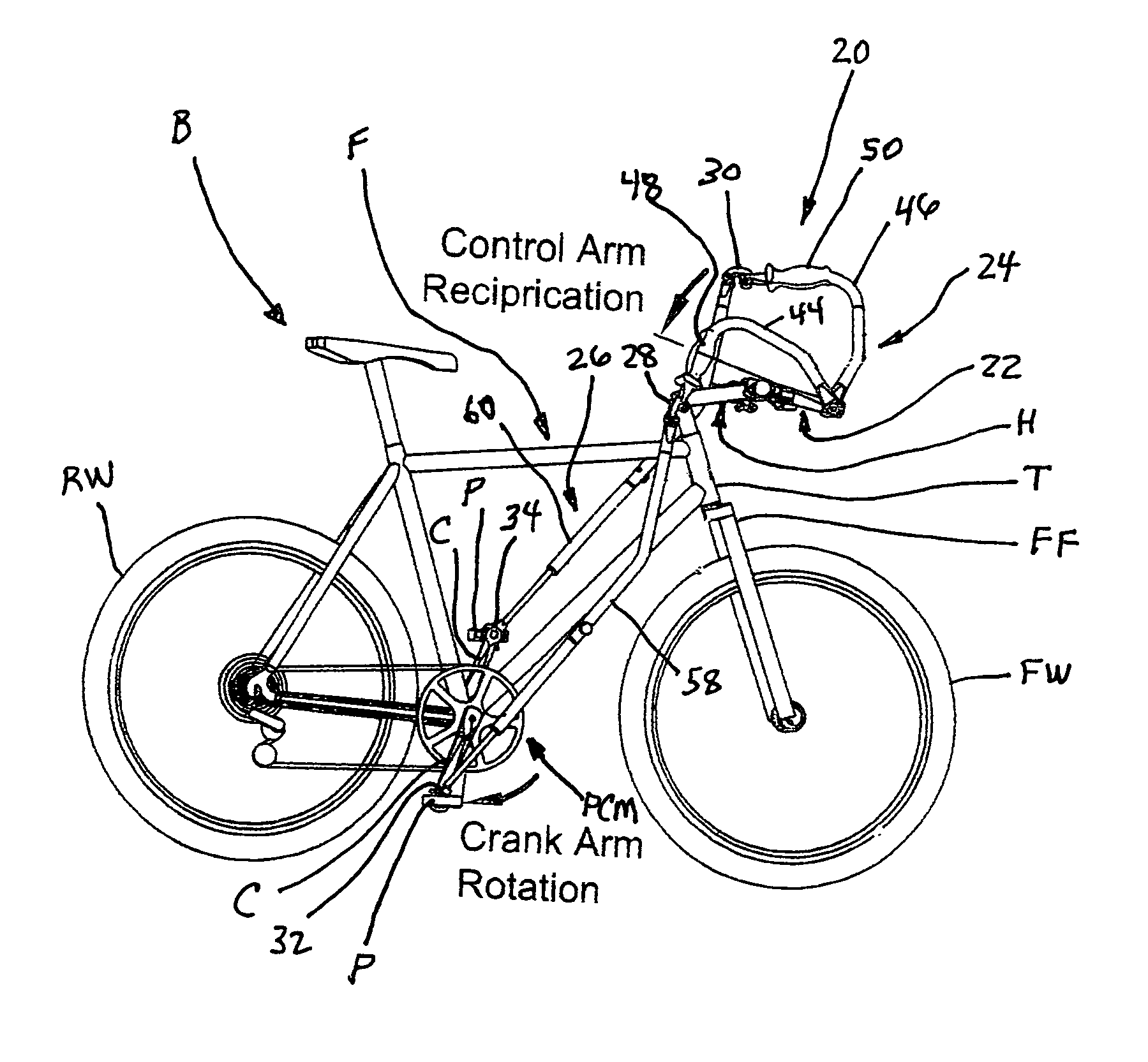
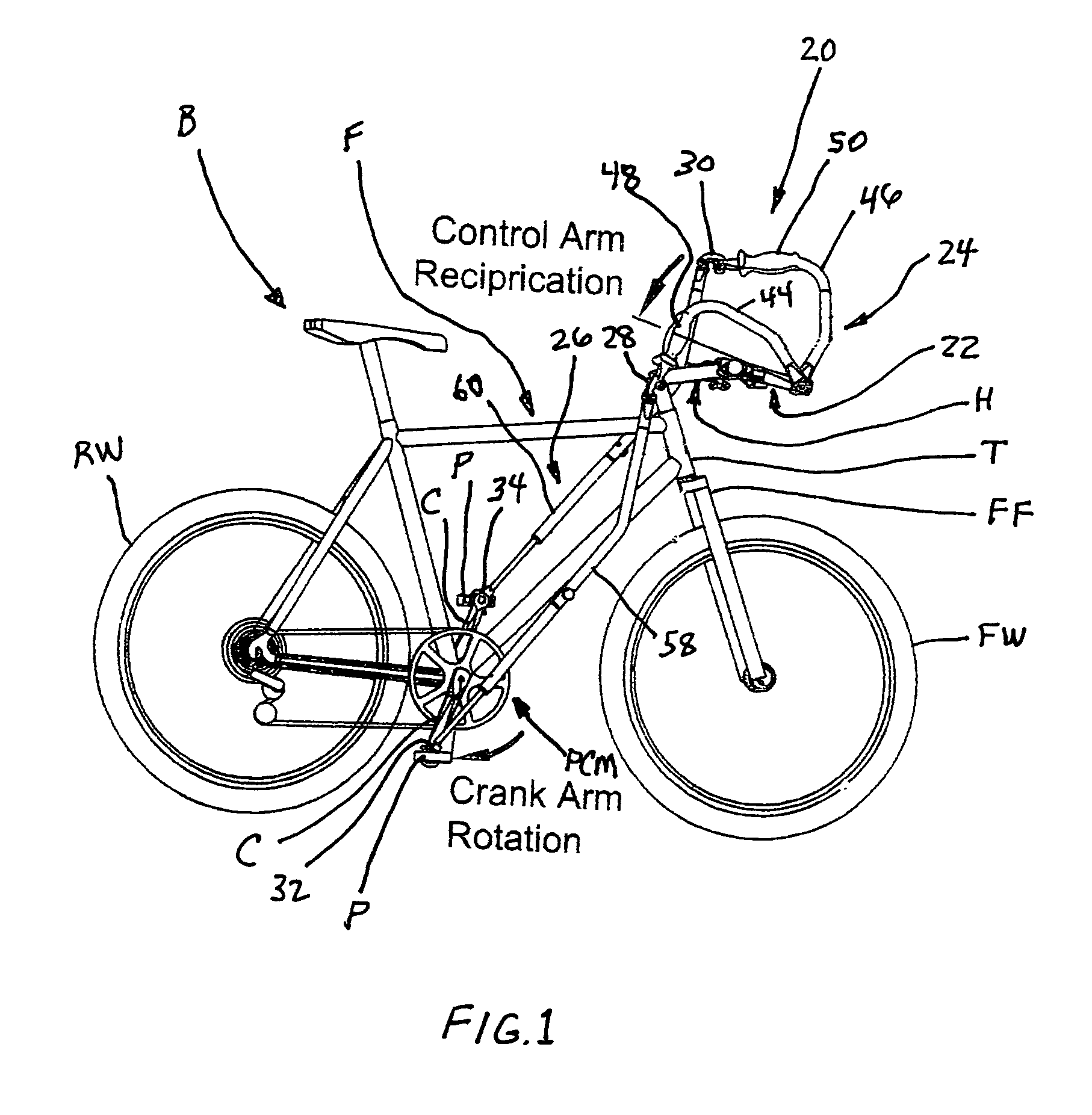
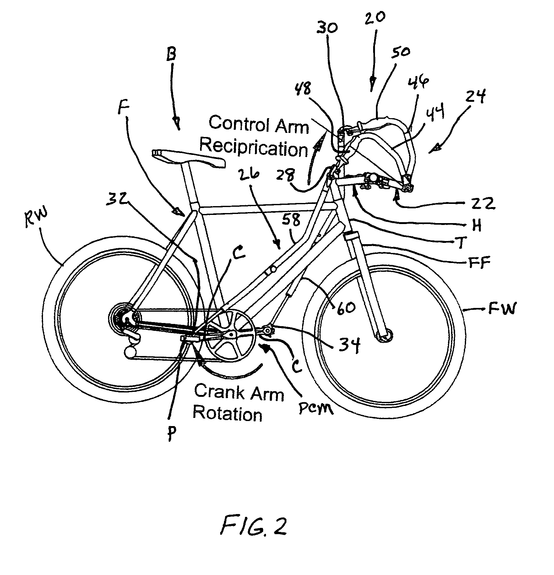
[0008]The present invention provides a bicycle arm-drive apparatus designed to overcome the above-described drawbacks and satisfy the aforementioned need. The arm drive apparatus disclosed herein is particularly suited for being mounted to a bicycle so that a rider can simultaneously use leg and arm power to drive it. The apparatus provides an effective arm-drive mechanism that minimally interferes with bicycle operation, and more specifically, with steering operation. The arm-drive mechanism is also designed to be effective while avoiding instability that can occur by arm forces applied near the steering mechanism. The apparatus of the present invention is also particularly designed to be easily removable from the bicycle. While the most widespread example of a vehicle using such arm-drive mechanism is a bicycle, the principles of the arm-drive apparatus of the present invention can be applied to other types of vehicles as well, such as tricycles or stationary exercise equipment. Therefore, it will be understood and assumed that while only the term “bicycle” is used hereinafter for the sake of brevity, this term will be taken in the broad sense as meaning all vehicles adapted to use such an arm-drive apparatus.
[0009]The present invention relates to an arm-drive apparatus which basically includes a stationary mounting structure, an arm drive input mechanism, a drive motion transmission mechanism, and a plurality of connectors. The stationary mounting structure positioned at the front of the bicycle attaches to the bicycle at one end of the mounting structure and provides two pivot locations at the other end of the mounting structure, one on each side of the structure. Attached at those pivot locations is the arm drive input mechanism for receiving the arm-power input, and which includes a pair of control arms with handgrips attached thereon. These control arms, which generally extend rearward and outward from their pivoted attach points on the mounting structure, allow the operator's arm power to assist in driving the bicycle through their fore-and-aft movement. The rear ends of the control arms connect to the drive motion transmission mechanism that operates in tandem with the control arms and which includes a pair of connecting rod assemblies positionable along opposite sides of the main frame of the bicycle and extending to a pair of bicycle pedals. The connectors mechanically and articulately link the connecting rod assemblies of the drive motion transmission mechanism to the bicycle pedals and to the rear ends of arm drive input mechanism control arms, thus allowing the fore-and-aft movement of the control arms to transmit through the connecting rod assemblies to the pedals. The apparatus of the present invention thereby enables the arm power of the operator to assist with pedaling drive operation of the bicycle.

Problems solved by technology

However, most arm-drive designs have achieved mixed results with respect to adaptability and effectiveness when attached to conventional bicycles.
Despite these prior art designs, several problems still remain in the field of arm-drive bicycle operation.
First, the previous devices often comprise a large or unwieldy lever system that interferes with normal bicycle pedaling and steering operation.
Moreover, these prior art designs do not appear to be easily attachable to a bicycle while leaving the existing steering system intact and also while providing an efficient and stable arm-driven mechanism for the rider.

Method used


Image

  • Bicycle arm-drive apparatus
  • Bicycle arm-drive apparatus
  • Bicycle arm-drive apparatus

Examples


Embodiment Construction

[0022]Referring to the drawings, and particularly to FIGS. 1-3, 4A and 4B, there is illustrated an exemplary embodiment of the arm-drive apparatus of the present invention, generally designated 20, for use by the operator of a conventional bicycle B or similar pedal driven machine. The bicycle B has a fore-and-aft main frame F, a head tube T fixedly connected on the forward end of the main frame F, a handlebar assembly H pivotally slotted into the head tube T, a front fork FF fixedly connected to the bottom end of the handlebar assembly H below the head tube T, a front wheel FW rotatably mounted to the front fork FF, a pair of pedal crank arms C rotatably mounted to the frame F at an intermediate bottom location thereon, pedals P rotatably mounted to shafts S attached to the ends of the pedal crank arms C. The pedal crank arms C rotatably drive the pedal crank mechanism PCM which in turn drives a rear wheel RW of the bicycle B and thereby propels the bicycle B.

[0023]The arm drive ap...


PUM


Abstract

A bicycle arm-drive apparatus includes a stationary mounting structure, an arm drive input mechanism, a drive motion transmission mechanism, and a plurality of connectors. One end of the mounting structure attaches to the front-center portion of the bicycle. The arm drive input mechanism includes a pair of control arms that pivotally attach to the other end of the mounting structure and generally extend rearward and outward from there. The operator grips each control arm, inputting arm power by driving them fore-and-aft. The drive motion transmission mechanism includes a pair of connecting rod assemblies running down opposite sides of the bicycle frame between the control arms and bicycle pedals. A plurality of connectors link the connecting rod assemblies to the pedals and control arms in order to transmit control arm fore-and-aft movement via the connecting rod assemblies to the pedals to enable the arm power to assist with bicycle pedaling.

Description

BACKGROUND OF THE INVENTION[0001]1. Field of the Invention[0002]The present invention generally relates to arm-power assisted bicycle operation and, more particularly, to an arm-drive apparatus mountable to a bicycle for providing upper body exercise through assisting leg power driving the bicycle.[0003]2. Description of the Prior Art[0004]A conventional bicycle is typically designed to be operated by movement of the legs of a rider / operator rotating a pedal crankshaft that drives the rear wheel of the bicycle. Arms and hands of the operator are typically relegated to steering the front wheel of the bicycle via a set of bicycle handlebars. In order to accomplish a more complete bicycle exercise routine, some designs have sought to augment the conventional leg operated bicycle design with a mechanism for using the arms as well. However, most arm-drive designs have achieved mixed results with respect to adaptability and effectiveness when attached to conventional bicycles.[0005]One re...

Claims


Application Information

Patent Timeline
Patent Type & Authority Patents(United States)
IPC IPC(8): B62M1/12
CPCB62M1/12
Inventor BARTLETT, CHRISTOPHER B.
Owner BARTLETT CHRISTOPHER B
Learn More