Semiconductor device and method of manufacturing the same

a semiconductor and semiconductor technology, applied in the field of semiconductor devices, can solve the problems of increasing parasitic capacitance between, reducing the bonding strength of the wire to the electrode pad, and affecting the quality of the device, so as to achieve the effect of increasing the parasitic capacitance of the electrode pad and valuing the high frequency characteristics

Inactive Publication Date: 2012-05-22
RENESAS ELECTRONICS CORP
View PDF4 Cites 4 Cited by
  • Summary
  • Abstract
  • Description
  • Claims
  • Application Information

AI Technical Summary

Benefits of technology

[0018]With a structure described above, a parasitic capacitance between a pad inputting / outputting a high frequency signal and a semiconductor device can be reduced, whereby signals can be favorably exchanged between the internal circuit and the outside. Further, probing is not performed and only a test after assembly is run on the pad inputting / outputting a high frequency signal, and thus damage is not caused by the probe, which also prevents a bonding strength between the pad and the wire from reducing.
[0020]According to the present invention, an increase in parasitic capacitance of the electrode pad to be connected to the circuit in which high frequency characteristics are valued can be suppressed.

Problems solved by technology

Therefore, when an electrode pad having a small area is used, if there remains damage caused by a probe on a surface of the electrode pad, there arises a problem in that bonding strength in the case of bonding the wire to the electrode pad is decreased.
An increase in area of the electrode pad leads to an increase in parasitic capacitance between the electrode pad and a semiconductor substrate.
In an electrode pad to be connected to a circuit in which high frequency characteristics are valued, such an increase in parasitic capacitance poses a problem.
Further, probing is not performed and only a test after assembly is run on the pad inputting / outputting a high frequency signal, and thus damage is not caused by the probe, which also prevents a bonding strength between the pad and the wire from reducing.

Method used


Image

  • Semiconductor device and method of manufacturing the same
  • Semiconductor device and method of manufacturing the same
  • Semiconductor device and method of manufacturing the same

Examples


Embodiment Construction

[0030]Hereinafter, an embodiment of the present invention is described with reference to the drawings. It should be noted that similar components are denoted by similar reference symbols in the respective drawings, and their descriptions are appropriately omitted.

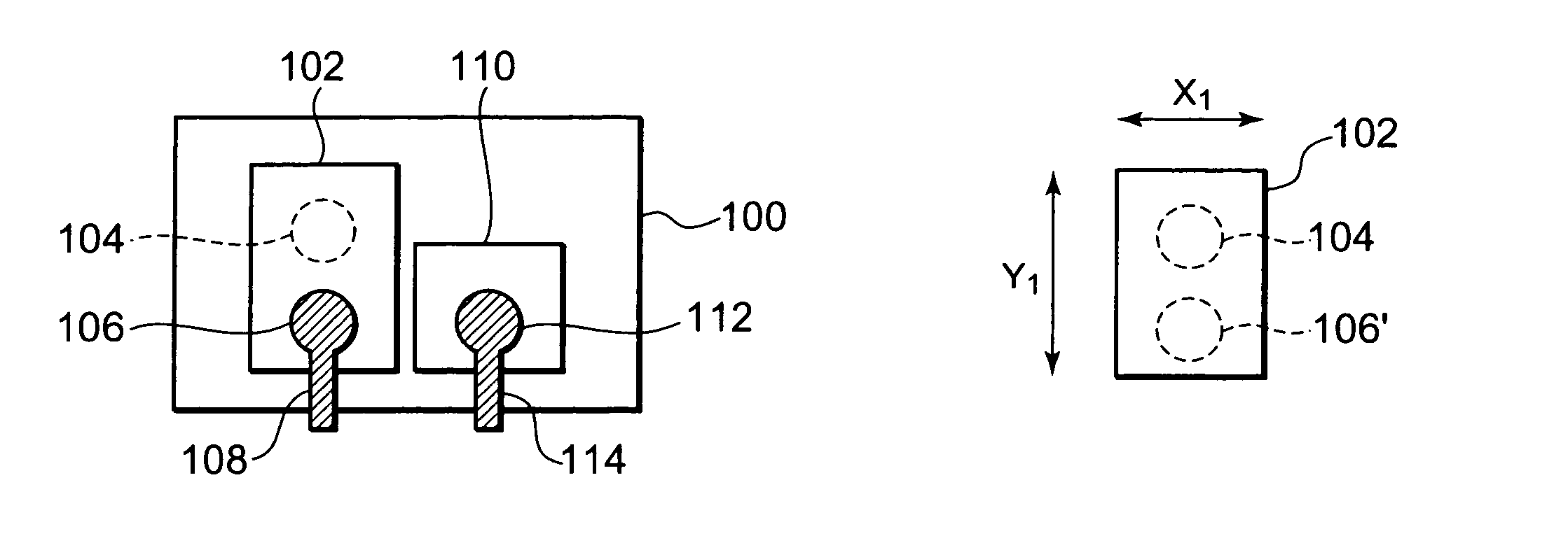
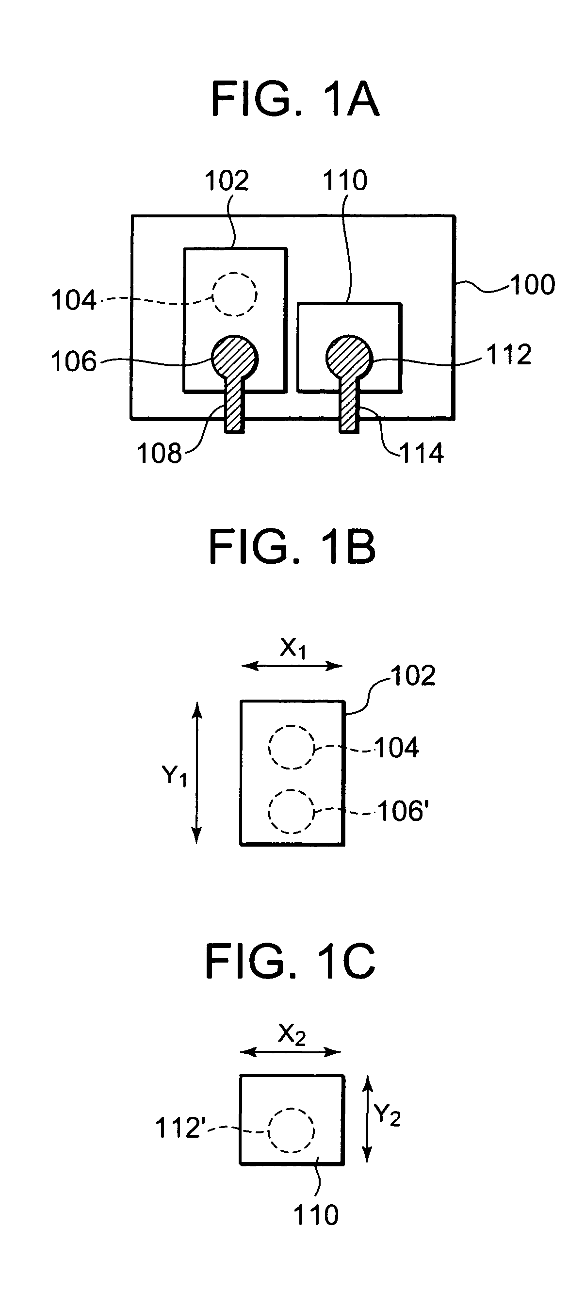
[0031]In this embodiment, a semiconductor device includes a semiconductor chip region provided with a plurality of internal circuits, and a plurality of electrode pads which are provided in the vicinity of an outer edge of the semiconductor chip region and are each electrically connected to any one of the plurality of internal circuits. In other words, the semiconductor device is constructed in a chip form, and then the electrode pad is provided in the vicinity of the chip end of the semiconductor chip. The plurality of electrode pads each have a function of bonding a wire for supplying a signal or power sent from the outside to the internal circuits provided on the semiconductor chip. In this embodiment, the plurality of e...


PUM


Abstract

A semiconductor chip includes a semiconductor chip region provided with a plurality of internal circuits, and a plurality of electrode pads provided proximate to an outer edge of the semiconductor chip region and each electrically connected to any one of the plurality of internal circuits. The plurality of electrode pads include: a long pad including a probe region with which a probe is brought into contact, and a bonding region provided in a position different from a position of the probe region, for bonding a wire; and a short pad for high frequency, which is formed to have a smaller pad area compared with the long pad and inputs / outputs a high frequency signal by employing a structure including the bonding region but the probe region.

Description

BACKGROUND OF THE INVENTION[0001]1. Field of the Invention[0002]The present invention relates to a semiconductor device and a method of manufacturing the same.[0003]2. Description of Related Art[0004]In recent years, along with a reduction in chip size, an area of an electrode pad used in probing and bonding has also been reduced. Besides, a ball area at a tip of a wire (gold wire) in the case of bonding the wire to the electrode pad has also been reduced, and thus a contact area between the ball and the electrode pad has been reduced as well. Therefore, when an electrode pad having a small area is used, if there remains damage caused by a probe on a surface of the electrode pad, there arises a problem in that bonding strength in the case of bonding the wire to the electrode pad is decreased.[0005]In order to prevent a decrease in bonding strength described above, there is used an electrode pad including a probe area with which the probe is brought into contact at a time of testing,...

Claims


Application Information

Patent Timeline
Patent Type & Authority Patents(United States)
IPC IPC(8): H01L29/40
CPCH01L23/5286H01L24/05H01L24/06H01L24/48H01L24/49H01L23/66H01L2224/05554H01L24/45H01L2224/04042H01L2224/05553H01L2224/05556H01L2224/05599H01L2224/0603H01L2224/06153H01L2224/45015H01L2224/45144H01L2224/48011H01L2224/48091H01L2224/4845H01L2224/48465H01L2224/48599H01L2224/49111H01L2224/49175H01L2224/49431H01L2224/85399H01L2924/01004H01L2924/01005H01L2924/01079H01L2924/01082H01L2924/20752H01L2924/30105H01L2924/30107H01L2924/3025H01L2924/00014H01L2924/01033H01L2924/01006H01L2924/20656H01L2924/00H01L2224/023H01L2224/48463H01L2924/0001
Inventor YAMAZAKI, TORU
Owner RENESAS ELECTRONICS CORP
Why Eureka
Try Eureka