Low numerical aperture (low-NA) solar lighting system

a solar lighting and numerical aperture technology, applied in the field of solar energy and lighting, can solve the problems of limiting the collection and transmission of solar light tubes, preventing widespread acceptance of solar lighting technology, and reducing so as to reduce the number of loss-inducing reflections, improve the luminosity, and optimize interior lighting

Inactive Publication Date: 2012-05-22
GU BINGWU
View PDF32 Cites 36 Cited by
  • Summary
  • Abstract
  • Description
  • Claims
  • Application Information

AI Technical Summary

Benefits of technology

[0007]Systems and methods provide for using natural light including sunlight and moonlight for optimized interior lighting. Incoming natural light is concentrated and then optimized to provide a greater luminosity than without optimization. The method of optimization aligns the concentrated sunlight to a low numerical aperture within the thermodynamic range to reduce the number of loss-inducing reflections through the light guide.

Problems solved by technology

Fundamental problems remain, however, that keep solar lighting technology from widespread acceptance.
Windows and skylight are limited by the shape and orientation of the building design.
Solar light tubes suffer an extensive loss from collection and transmission limitations.
Large diameter tubes are required because the light tube inlet is limited to collecting the solar light coming through its cross-section.
Fiber optic bundles, while losing less light than solar tubes, are very expensive for general lighting applications.

Method used


Image

  • Low numerical aperture (low-NA) solar lighting system
  • Low numerical aperture (low-NA) solar lighting system
  • Low numerical aperture (low-NA) solar lighting system

Examples


embodiment 400

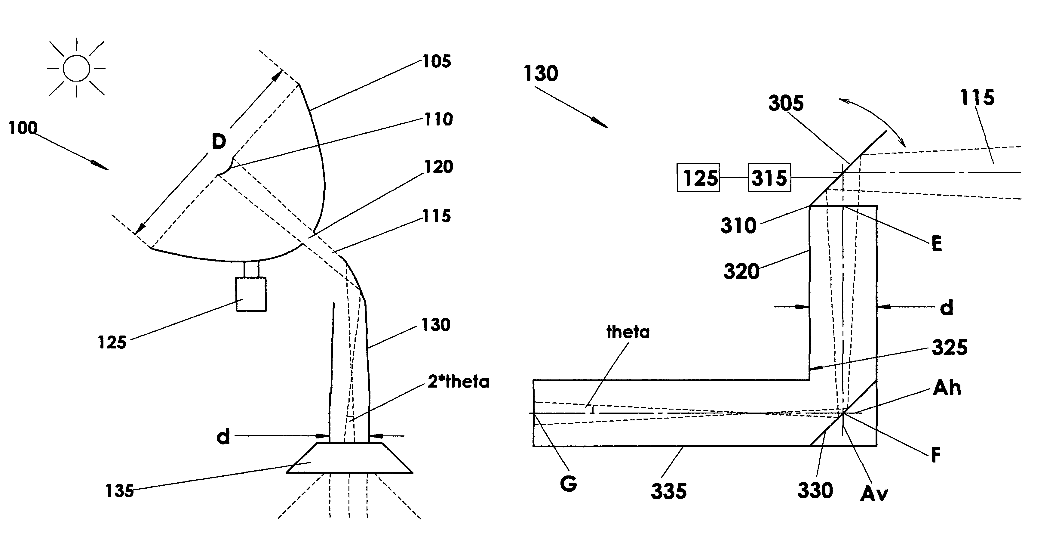
[0050]FIG. 4 shows an alternate embodiment 400 of the low numerical aperture optimizer 130 for the low numerical aperture lighting system 100. The low numerical aperture optimizer may further comprise a second highly reflective mirror 325, and a diverging refractive lens 410 (a.k.a. a negative lens). This embodiment may comprise the primary and secondary light concentrator (not shown here) as shown in FIG. 1 and FIG. 2.

[0051]In some installations, the configuration of the light source, the building and the primary light concentrator may be such that the low-NA optimizer 130 is not above the lighting fixture 135. In some of these embodiments, the alternate embodiment 400 of the low numerical aperture optimizer may be suitable.

[0052]As shown in FIG. 4, the concentrated light 115 enters the low-NA optimizer 400 along an optical axis “Av.” To achieve an optimal low-NA concentrated light, there may be one or more of the highly reflective mirrors 305 and 325 to direct the concentrated lig...

embodiment 500

[0057]FIG. 5 shows a different embodiment 500 of the low numerical aperture optimizer 130 for the low numerical aperture lighting system 100. This embodiment may comprise the highly reflective mirror 305, the highly reflective mirror hinge 310, the highly reflective mirror controller 315, the solar tracker 125, a semi-circular light guide 505, and the highly reflective film 325 (not shown). This embodiment may comprise the primary and secondary light concentrator (not shown here) as shown in FIG. 1 and FIG. 2.

[0058]In lieu of the light guide mirror 330, the low-NA optimizer 500 has an inside coating of the highly reflective film 325 to optimize the concentrated light 115 to a low-NA. Once again, the optical axis lines Av and Ah are perpendicular to each other, with the semi-circular light guide 505 shaped to optimize the low numerical aperture of the concentrated light within the thermodynamic limit.

embodiment 600

[0059]FIG. 6 shows another embodiment 600 of the low numerical aperture optimizer 130 for the low numerical aperture lighting system 100. The low numerical aperture optimizer 600 may comprise the primary and secondary light concentrator (not shown here) as shown in FIG. 1 and FIG. 2. This embodiment may comprise the highly reflective mirror 305, connected to the highly reflective mirror controller 315, which works in coordination with solar tracker 125 to align highly reflective mirror 305 so that concentrated light 115 enters the upper light guide 605 properly aligned to optical axis Av. The embodiment 600 may also comprise the light guide mirror 330 and lower light guide 335, although these are optional as described in FIG. 3.

[0060]This embodiment of the low-NA optimizer 600 differs from other embodiments in that the upper light guide 605 may be in the shape of a reverse compound parabolic concentrator (CPC) or other shape of a reverse conic concentrator. The upper light guide 605...


PUM


Abstract

A low numerical aperture (low-NA) light concentration and transmission system collects, concentrates and transmits light for interior illumination. A solar tracker aligns a primary light concentrator to collect light and direct the light to a secondary light concentrator and a filter for removing ultraviolet and infrared radiation. On exiting the secondary light concentrator, the optical axis of the concentrated light is aligned to optimize the numerical aperture of the concentrated light with a numerical aperture (NA) optimizer having a light guide to direct the concentrated light to an interior luminaire. The method of the low numerical aperture transmission of light has the advantages of fewer reflections in the light guide, low loss, low cost, and easy installation and operation.

Description

CROSS-REFERENCE TO RELATED APPLICATIONS[0001]This application claims the benefit of priority of U.S. Provisional Application Ser. No. 61 / 094,117 titled “Low Numerical Aperture (Low-NA) Solar Lighting System” filed Sep. 4, 2008, which is hereby incorporated by reference. This application also claims the benefit of priority of U.S. Provisional Application Ser. No. 61 / 094,113 titled “One-axis tracking concentrating photovoltaic and solar hot water hybrid system” filed Sep. 4, 2008, which is hereby incorporated by reference. This application also claims the benefit of priority of U.S. Provisional Application Ser. No. 61 / 094,115 titled “Alternating current electricity generation from concentrated sunlight” filed Sep. 4, 2008, which is hereby incorporated by reference. This application also claims the benefit of priority of U.S. Provisional Application Ser. No. 61 / 094,120 titled “Solar lighting system with one-axis tracking” filed Sep. 4, 2008, which is hereby incorporated by reference. T...

Claims


Application Information

Patent Timeline
Patent Type & Authority Patents(United States)
IPC IPC(8): G02B17/00
CPCH01L31/058G02B3/08G02B5/0808G02B5/10G02B17/06G02B17/061G02B27/095G01S3/781G01S3/7861G02B19/0042G02B19/0023G02B19/0033F21S11/00H01L31/054H01L31/0543H02S40/44H01L31/0547H01L31/0522H01L31/0524H01L31/0525F24J2/067F24J2/10Y02E10/52F24J2/085F24S23/12F24S23/31F24S23/70Y02E10/60
Inventor GU, BINGWU
Owner GU BINGWU
Why Eureka
Try Eureka