Calibration system, calibrating method, and correction processing program

a calibration system and calibration method technology, applied in the field of calibration system, calibrating method, color correction correction processing program, can solve the problems of affecting the accuracy of calibration, so as to enhance the accuracy of calibration and suppress the influence of density unevenness

Active Publication Date: 2012-05-29
KONICA MINOLTA BUSINESS TECH INC
View PDF13 Cites 7 Cited by
  • Summary
  • Abstract
  • Description
  • Claims
  • Application Information

AI Technical Summary

Benefits of technology

[0010]The present invention has been achieved in view of the above-mentioned problems, and the objects of the present invention are to provide a calibration system, calibrating method, and correction processing program which can suppress the influence of density unevenness and can enhance the precision of calibration.

Problems solved by technology

Secondly, the printed measurement patches are subjected to color measurement by a calorimetric device.
However, in an image forming apparatus to print the measurement patches, periodic density unevenness or accidental density unevenness may occur due to rotational unevenness of a photoreceptor or an intermediate transfer member.
Therefore, at the time of printing a sheet (hereafter, referred to a patch sheet) on which the measurement patches are arranged in a predetermined direction, if such density unevenness occurs, the problem that the precision of a calibration gets worse, eventually arises.
However, in the method of calculating the average values of the calorimetric values, since it is necessary to print plural patch sheets, there is a problem to consume sheets uneconomically.
Moreover, when density unevenness occurred in the same position, even if the average values of the calorimetric values are calculated, the influence of the density unevenness cannot be suppressed.
As a result, there is a problem that the precision of calibration gets worse.
Moreover, the method of Japanese Patent Unexamined Publication No. 2001-94803 merely avoid the bias of the periodic density unevenness to one color and does not perform correction for the occurred density unevenness.
Therefore, there is a problem that the influence of the density unevenness appears on all the colors.
As a result, there is a problem that the precision of calibration gets worse.

Method used


Image

  • Calibration system, calibrating method, and correction processing program
  • Calibration system, calibrating method, and correction processing program
  • Calibration system, calibrating method, and correction processing program

Examples


example

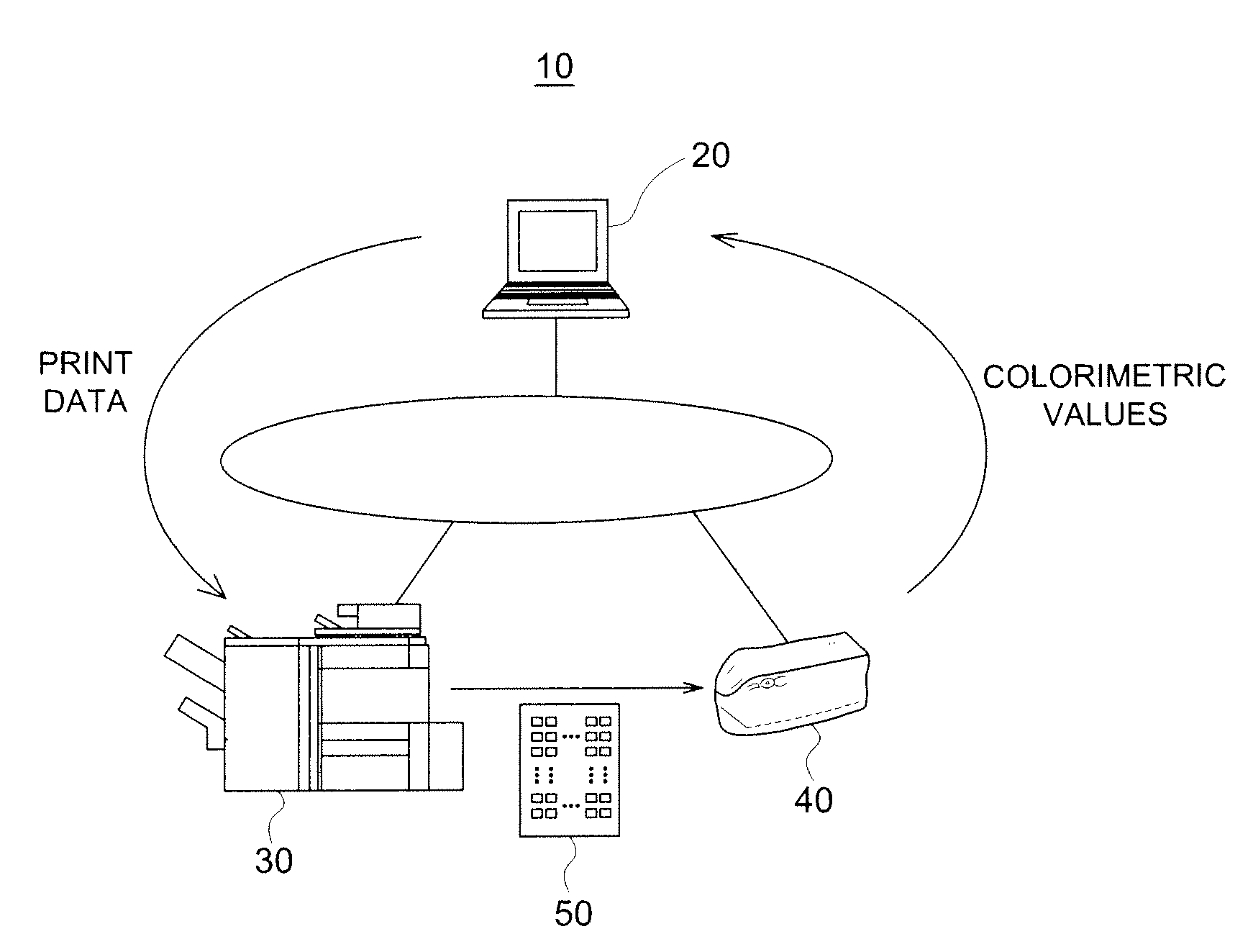
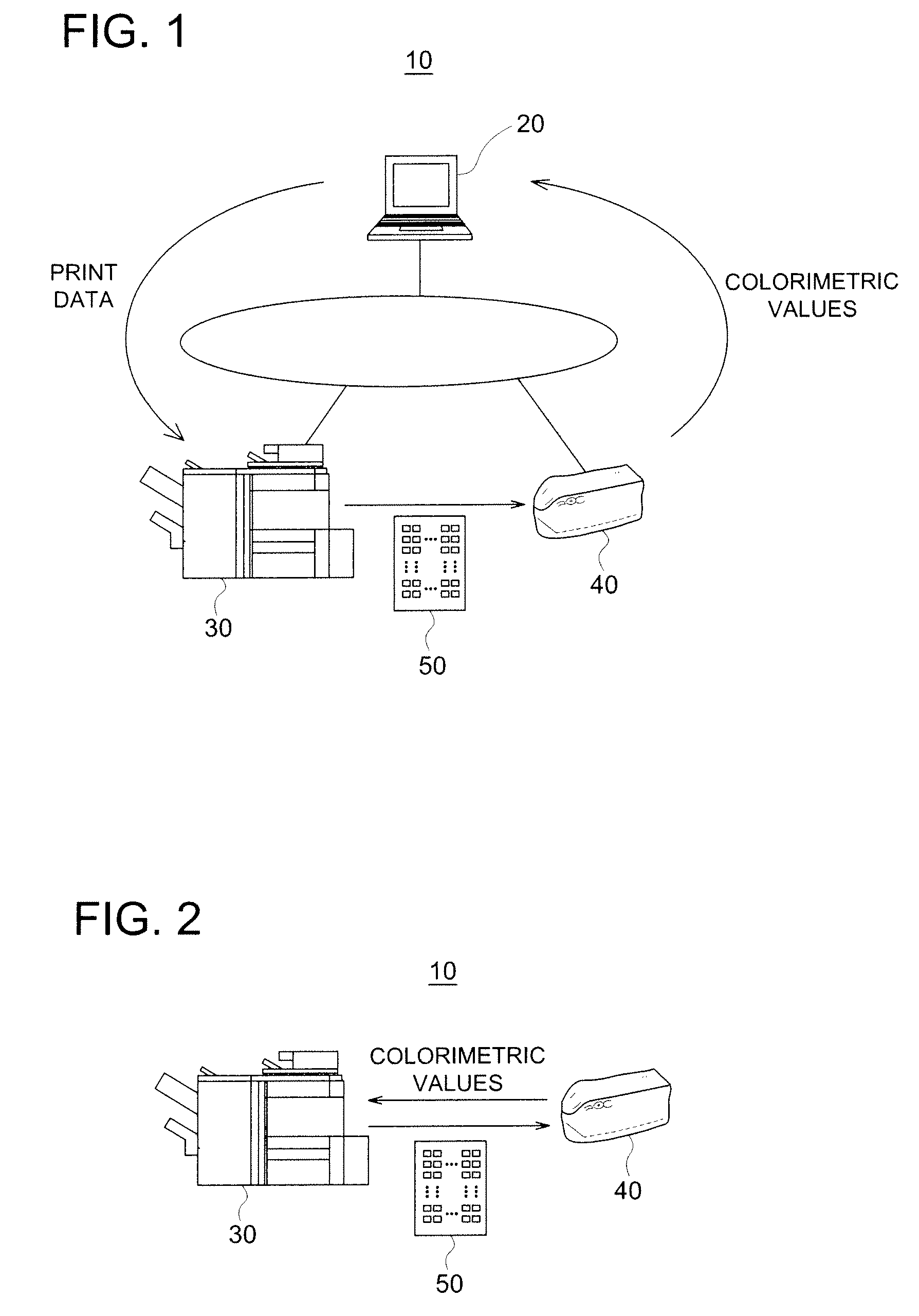
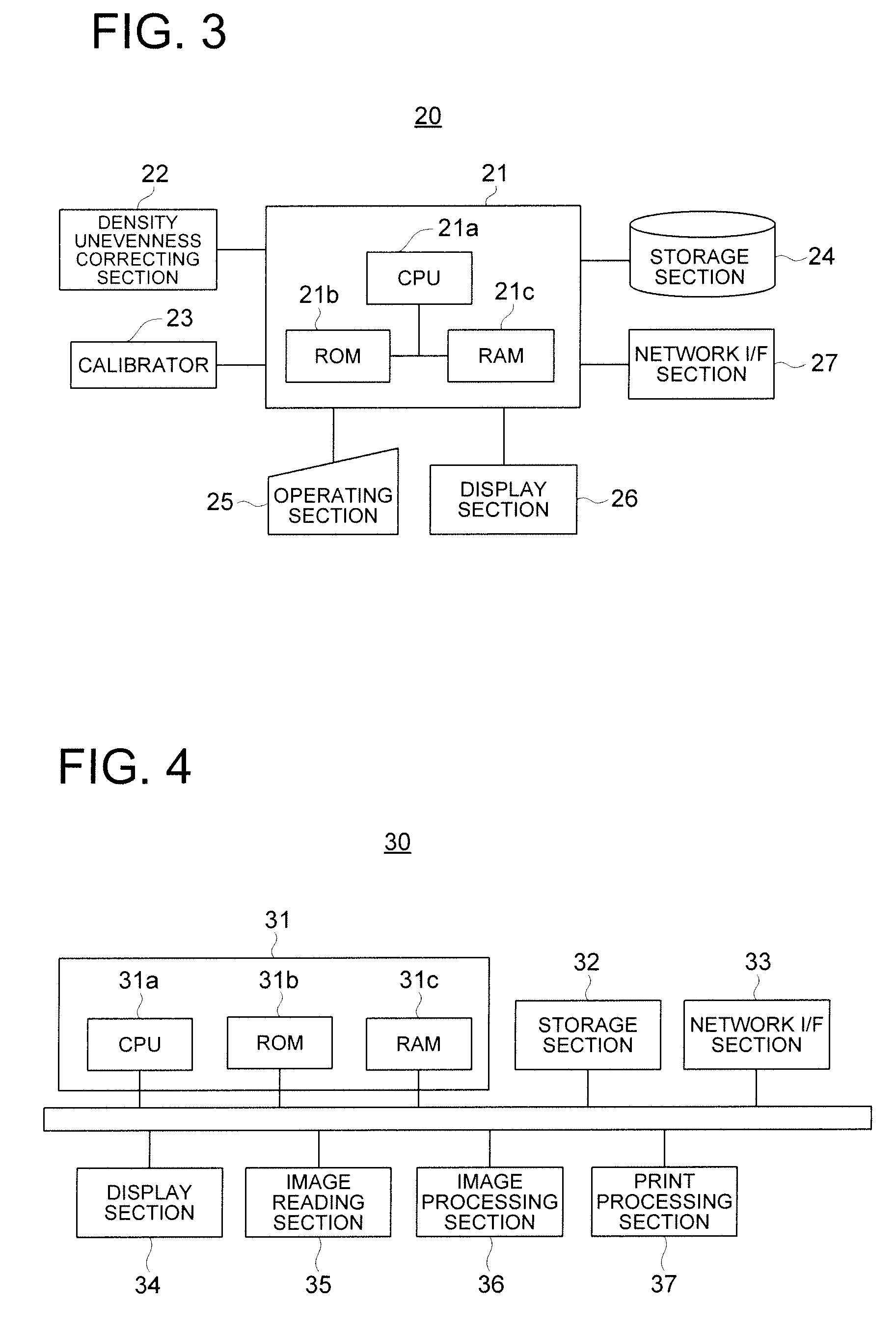
[0047]In order to explain in detail about the above-mentioned embodiment of the present invention, the calibration system, calibrating method, and correction processing program according to one example of the present invention are explained with reference to FIGS. 1 through 15. FIGS. 1 and 2 each is a schematic illustration showing the structure of the calibration system of this example. Further, FIG. 3 is a block diagram showing the structure of a host computer, and FIG. 4 is a block diagram showing the structure of an image forming apparatus, and FIG. 5 is an illustration showing an outline operation of the calibration system. Moreover, FIGS. 6 through 8 are flow chart diagrams showing the procedure of the calibration of this example, and FIGS. 9 through 15 are illustrations showing the structural example of patch sheets of this example.

[0048]As shown in FIG. 1, a calibration system 10 of this example comprises one or plural client apparatuses (hereafter, referred to a host comput...


PUM

PropertyMeasurementUnit
densitiesaaaaaaaaaa
densityaaaaaaaaaa
colorimetricaaaaaaaaaa

Abstract

In a calibration system for conducting calibration by using a patch sheet produced on the basis of data to form measurement patches with respective different densities arranged in a predetermined direction and reference patches with a constant density arranged in the vicinity of the measurement patches for each color toner, the calibration system is provided with a correcting section to correct, on the basis of the calorimetric values of the reference patches, the calorimetric values of the measurement patches arranged in the vicinity of the reference patches.

Description

[0001]This application is based on Japanese Patent Application No. 2008-063347 filed on Mar. 12, 2008 in Japanese Patent Office, the entire content of which is hereby incorporated by reference.BACKGROUND OF THE INVENTION[0002]The present invention relates to a calibration system, calibrating method, and correction processing program for color correction.[0003]Image forming apparatus equipped with a color printing function, such as a copying machine and a composite machine (MFP: Multi Function Peripheral), has been used widely. In this image forming apparatus, the following process is conducted: image information is generated based on print data transmitted from a host computer; an electrostatic latent image is formed on a photoreceptor that has been electrically charged by irradiating light based on the image information; the electrostatic latent image is developed into a toner image by the adhesion of electrically charged toner; and the toner image is transferred onto a sheet throu...

Claims


Application Information

Patent Timeline
Patent Type & Authority Patents(United States)
IPC IPC(8): G03F3/08
CPCH04N1/00015H04N1/00023H04N1/00031H04N1/00045H04N1/00063H04N1/00087H04N1/6033H04N2201/0082
Inventor FUKUHARA, TAKAHIRO
Owner KONICA MINOLTA BUSINESS TECH INC
Why Eureka
Try Eureka