Sensor device for and a method of sensing magnetic particles

a technology of magnetic particles and sensors, applied in the field of sensors, can solve problems such as insufficient accuracy of measurement results, and achieve the effects of reducing resistance, dissipating more thermal energy, and erasing remaining magnetizations

Active Publication Date: 2012-05-29
SIEMENS HEALTHINEERS NEDERLAND BV
View PDF8 Cites 9 Cited by
  • Summary
  • Abstract
  • Description
  • Claims
  • Application Information

AI Technical Summary

Benefits of technology

[0024]According to an exemplary embodiment of the invention, an off-chip magnetic field actuation unit may generate a time-dependent or time-varying magnetic field for guiding the magnetic particles relative to the sensing unit in a manner that an undesired interaction between different magnetic particles can be suppressed. Particularly, an oscillation-, pulsed-, step function-, or triangle function-like magnetic field includes time intervals during which such an attraction between magnetic particles is inhibited and includes time intervals during which collective actuation of magnetic particles is promoted. For instance, pauses during which no magnetic field acts on magnetic particles may be included in the time-dependent magnetic field characteristics. Thereby, it may be possible to prevent a clustering of magnetic particles for instance during accumulating the magnetic particles prior to a sensor event and / or between bound and unbound magnetic particles after a sensor event has occurred during a procedure by which unbound particles shall be washed out by magnetic forces. Therefore, the accuracy of the device may be significantly improved since undesired magnetic clustering may be avoided.
[0074]The device, methods and systems described herein can be used as rapid, robust, and easy to use point-of-care biosensors for small sample volumes. The reaction chamber can be a disposable item to be used with a compact reader. Also, the device, methods and systems according to embodiments of the present invention can be used in automated high-throughput testing. In this case, the reaction chamber is e.g. a well plate or cuvette, fitting into an automated instrument.

Problems solved by technology

However, sufficient accuracy of measurement results may still be problematic under undesired circumstances.

Method used


Image

  • Sensor device for and a method of sensing magnetic particles
  • Sensor device for and a method of sensing magnetic particles
  • Sensor device for and a method of sensing magnetic particles

Examples


Embodiment Construction

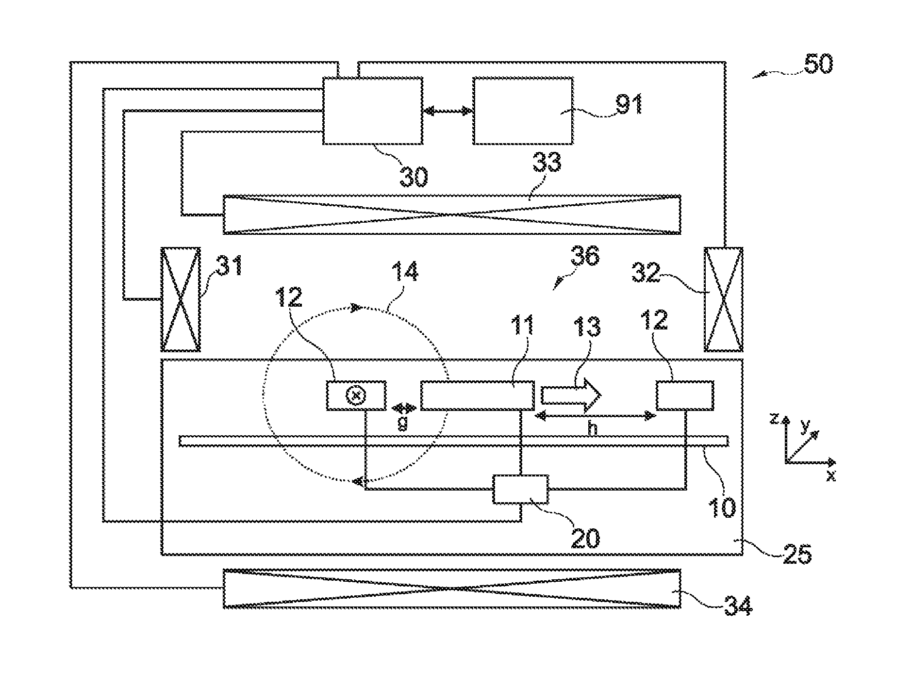
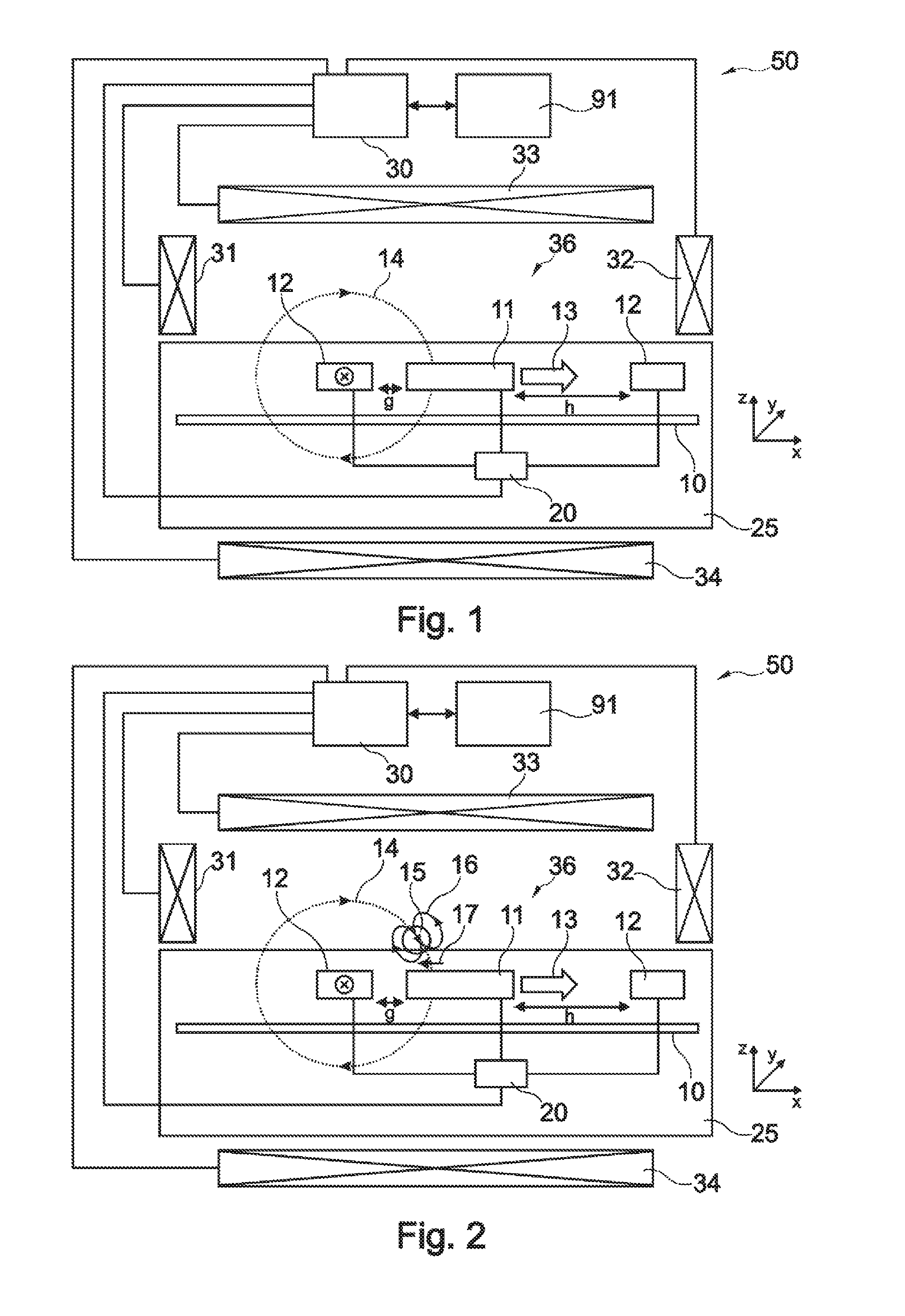
[0084]The illustration in the drawing is schematically. In different drawings, similar or identical elements are provided with the same reference signs.

[0085]In a first embodiment the device according to the present invention is a biosensor and will be described with respect to FIG. 1 and FIG. 2. The biosensor detects magnetic particles in a sample such as a fluid, a liquid, a gas, a visco-elastic medium, a gel or a tissue sample. The magnetic particles can have small dimensions. With nano-particles are meant particles having at least one dimension ranging between 3 nm and 5000 nm, preferably between 10 nm and 3000 nm, more preferred between 50 nm and 1000 nm. The magnetic particles can acquire a magnetic moment due to an applied magnetic field (for instance they can be paramagnetic). The magnetic particles can be a composite, for instance consist of one or more small magnetic particles inside or attached to a non-magnetic material. As long as the particles generate a non-zero respo...


PUM

PropertyMeasurementUnit
frequencyaaaaaaaaaa
frequencyaaaaaaaaaa
frequencyaaaaaaaaaa

Abstract

A sensor device for sensing magnetic particles, the sensor device including a substrate and a sensing unit provided on and / or in and / or near the substrate. The sensing unit is configured to sense a detection signal indicative of the presence of the magnetic particles. The sensor device further includes a magnetic field control unit which may be provided off the substrate and is configured to generate a time-dependent magnetic field for interaction with the magnetic particles.

Description

FIELD OF THE INVENTION[0001]The invention relates to a sensor device.[0002]The invention further relates to a method of sensing magnetic particles.[0003]Moreover, the invention relates to a program element.[0004]Further, the invention relates to a computer-readable medium.BACKGROUND OF THE INVENTION[0005]A biosensor may be a device for the detection of an analyte that combines a biological component with a physicochemical or physical detector component.[0006]Magnetic biosensors may use the Giant Magnetoresistance Effect (GMR) for detecting biological molecules being magnetic or being labeled with magnetic beads.[0007]In the following, biosensors will be explained which may use the Giant Magnetoresistance Effect.[0008]WO 2005 / 010542 discloses the detection or determination of the presence of magnetic particles using an integrated or on-chip magnetic sensor element. The device may be used for magnetic detection of binding of biological molecules on a micro-array or biochip. Particular...

Claims


Application Information

Patent Timeline
Patent Type & Authority Patents(United States)
IPC IPC(8): G01N33/543
CPCB82Y25/00G01N27/745G01N33/54326G01N33/54373G01R33/07G01R33/093G01R33/12G01R33/1269G01R33/1276
Inventor KAHLMAN, JOSEPHUS ARNOLDUS HENRICUS MARIAVAN LANKVELT, PETRUS JOHANNES WILHELMUSNIEUWENHUIS, JEROEN HANSIMMINK, ALLBERT HENDRIK JAN
Owner SIEMENS HEALTHINEERS NEDERLAND BV
Why Eureka
Try Eureka