

Analysis Device For Gaseous Samples And Method For Verification of Analytes In A Gas
- Summary
- Abstract
- Description
- Claims
- Application Information
AI Technical Summary
Benefits of technology
Problems solved by technology
Method used
Image

Examples
Embodiment Construction
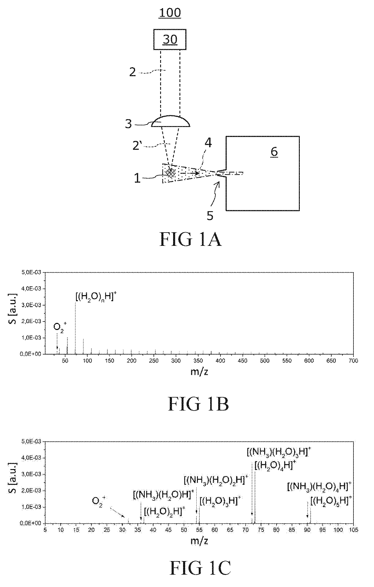
[0077]FIG. 1A is a schematic illustration of an analysis device 100 for gaseous samples. The analysis device 100 includes a mass spectrometer 6 and a laser irradiation unit that has a laser 30 and a focusing optical unit depicted as a lens 3. The mass spectrometer 6 has an inner measurement chamber and an inlet 5 leading into the measurement chamber. For sake of clarity, no detailed illustration of the structure of the mass spectrometer 6, laser 30, and focusing optical unit 3 is provided.
[0078]The experimental results presented below were determined with an API-HTOF MS time-of-flight mass spectrometer (Tofwerk, Thun, Switzerland) for the mass spectrometer 6 and a Conqueror 3-LAMBDA laser (Compact Laser Solutions GmbH, Berlin, Germany), i.e., a diode-pumped Nd:YVO4 laser for the laser 30, wherein the wavelength of the laser beams used was λ=532 nm. The API-HTOF MS time-of-flight mass spectrometer has internal pumps (three pump stages) with which gas may be drawn in via the inlet 5. ...
PUM
 Abstract
Description
Claims
Application Information