
Microscale high-frequency vacuum electrical device

a vacuum electrical and micro-scale technology, applied in the manufacture of electrode systems, transit-tube cathodes, electric discharge tubes/lamps, etc., can solve the problems of increasing undesired electrical interactions, and achieve the effect of simplifying device tuning, reducing undesired electrical interactions among device signals, and simplifying circuit design

Active Publication Date: 2010-06-15
WISCONSIN ALUMNI RES FOUND
View PDF13 Cites 0 Cited by
  • Summary
  • Abstract
  • Description
  • Claims
  • Application Information

AI Technical Summary

Benefits of technology

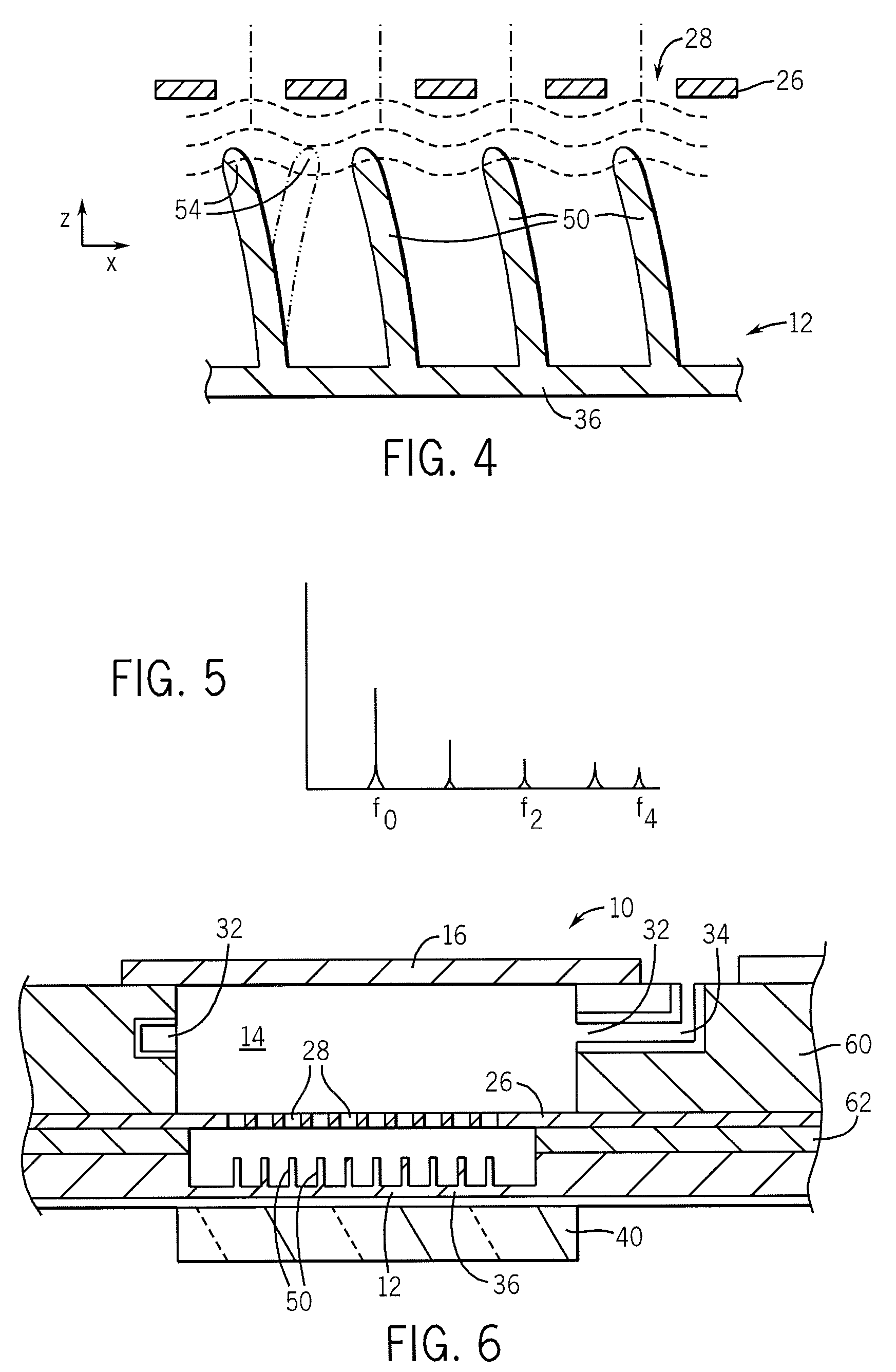
The present invention provides a microscale vacuum electrical device that employs mechanical modulation to control an electron beam. This offers the possibility of simplified device tuning as compared to conventional devices. The device includes an actuator that receives a first signal to modulate a relative location of a cathode, for example with respect to a grid or the anode, at a frequency greater than 50 kilohertz and for nanoscale devices to frequencies of up to 10 GHz, to modulate the electron beam. The actuator may be a piezoelectric device, which is compatible with microscale devices and operates at high frequency. The actuator may move the cathode, and the modulation of the electron beam may be at a harmonic frequency of the first signal driving the actuator. The cathode may include an array of field-emitting pillars, which improve electron emissivity and provide better electron beam modulation. The grid may include apertures aligned with the pillars, which provide flexibility in modulating the electron beam. The modulation of the electron beam by the pillars may be at a harmonic of a frequency of movement of a membrane forming the cathode. The cathode and the pillars may be formed from a doped semiconductor, which makes it easy to fabricate the device using conventional integrated circuit techniques. The tips of the pillars may be coated with a material increasing the electron emissions of the pillars, which provides a high emissivity surface.

Problems solved by technology

The small scale of such devices allows extremely high frequency signals to be generated and controlled, but also raises a number of practical problems including tuning the device when used as an oscillator, which may require changing a microscale physical cavity size.
Small scale devices also present problems of creating a hot cathode for thermionic emission, and problems inherent in the close spacing of the elements, for example the control grid to the cathode, such as may increase undesired electrical interactions.

Method used


Image

  • Microscale high-frequency vacuum electrical device
  • Microscale high-frequency vacuum electrical device
  • Microscale high-frequency vacuum electrical device

Examples


Embodiment Construction

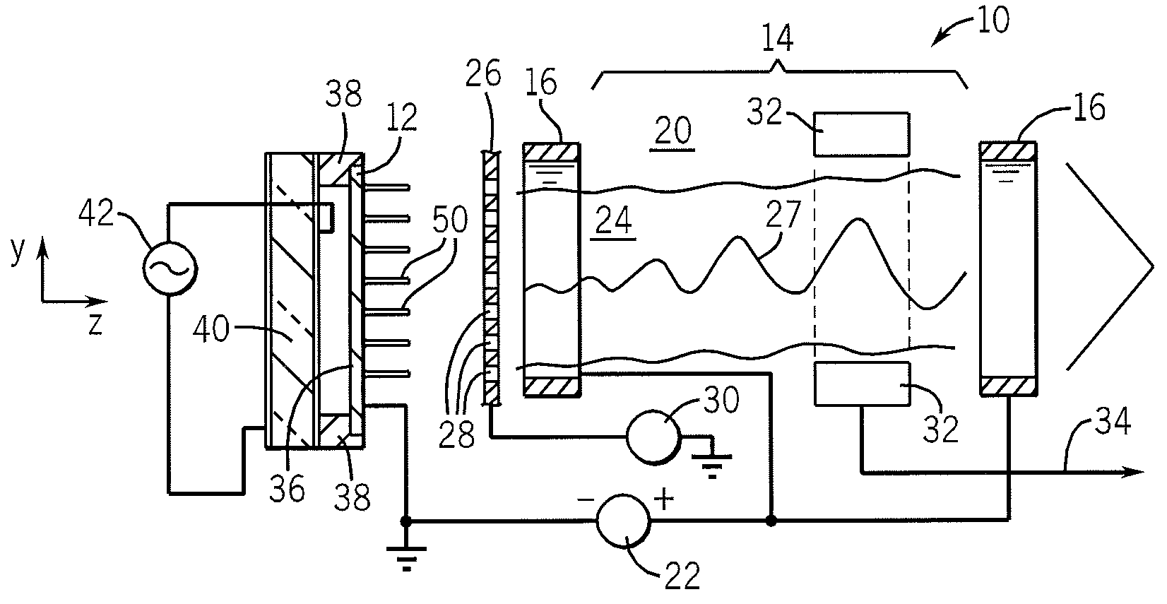
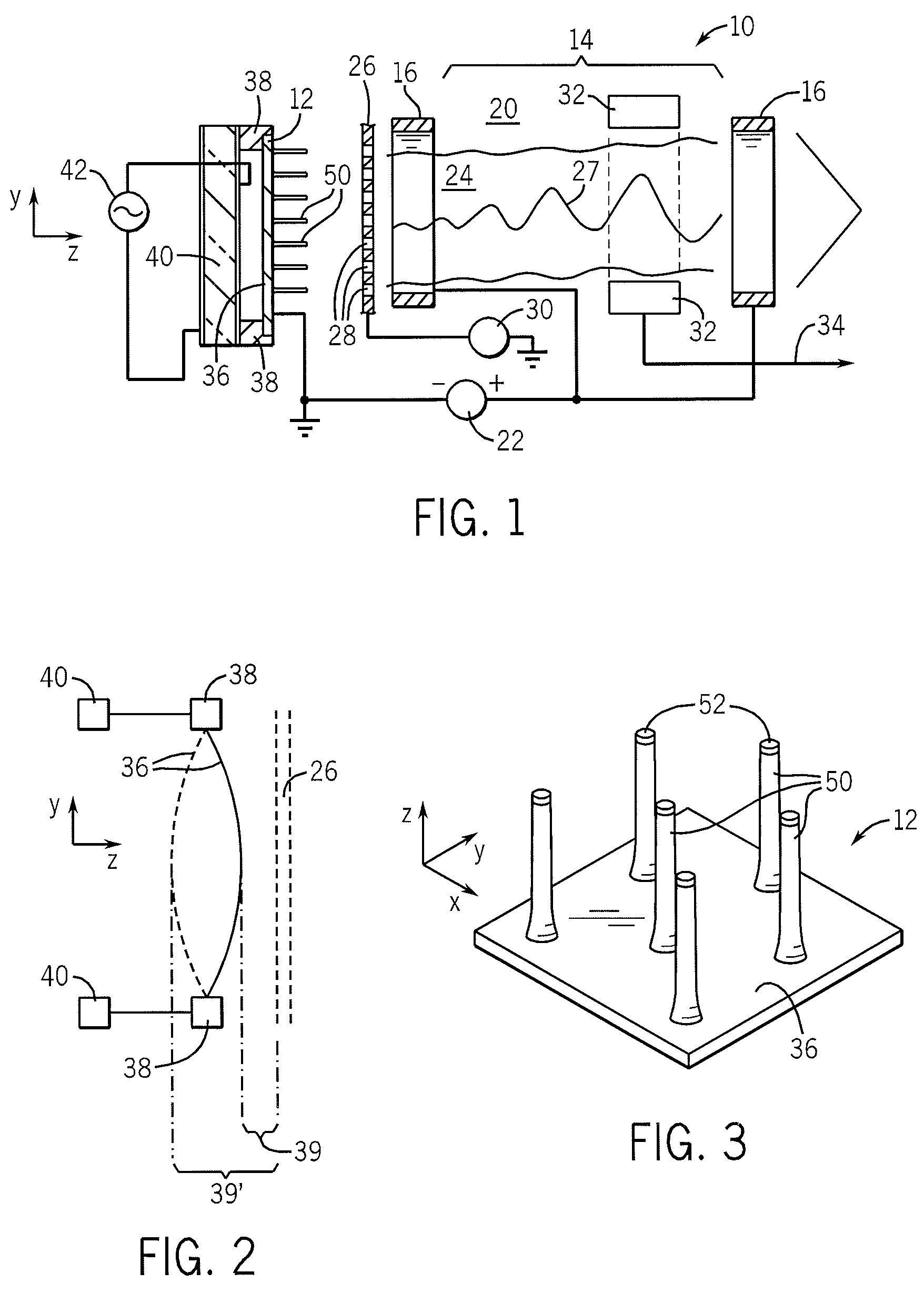
[0041]Referring now to FIG. 1, one embodiment of the invention may provide a klystrode 10 having a conductive cathode 12 opposed with one or more conductive anodes 16, defining between them a “drift space”14, all held within an evacuated housing 20. The cathode 12 may be biased with respect to the anodes 16 by a DC bias source 22 as is understood in the art. Under the influence of the bias source 22, electrons are emitted from the cathode 12 and drawn in an electron beam 24 along a z-axis into the drift space 14.

[0042]The surface of the cathode may be of a type, as will be described below, to promote non-thermionic, low-temperature emission of electrons (field emissions) to provide for “cold cathode” operation. The cold operation of the cathode 12 allows it to be placed close to a grid 26, positioned between the cathode 12 and anode 16 so that electrons of the electron beam 24 must pass through apertures 28 in the grid before reaching the drift space 14.

[0043]In one possible operati...


PUM


Abstract

A microscale vacuum electronic device (10) provides for a mechanical modulation of cathode (12) position with respect to the anode position, the anode electrically biased with respect to the cathode and held in an evacuated housing with the cathode, allowing improved high-frequency modulation of an electron beam (24) useful for vacuum electronic devices such as klystrons, klystrodes, and high frequency triodes.

Description

CROSS-REFERENCE TO RELATED APPLICATIONS[0001]This application claims the benefit of U.S. provisional application 60 / 843,991 filed Sep. 12, 2006 hereby incorporated by reference.STATEMENT REGARDING FEDERALLY SPONSORED RESEARCH OR DEVELOPMENTBackground of the Invention[0002]The present invention relates generally to high frequency vacuum electronics, including devices such as klystrons, klystrodes, and high frequency triodes and more specifically to a microscale vacuum electronic device employing mechanical modulation.[0003]High-powered, high-frequency electrical signals may be created and controlled by vacuum electrical devices including vacuum tubes such as triodes, and traveling wave tubes, including generally magnetrons, klystron, klystrodes and the like.[0004]One such device, the klystron, provides a cathode producing an electron beam directed toward an anode and then into a drift space. A high-frequency signal, for example at microwave frequencies, is introduced into a resonant ...

Claims


Application Information

Patent Timeline
Patent Type & Authority Patents(United States)
IPC IPC(8): H01J9/04
CPCH01J25/02H01J23/04
Inventor BLICK, ROBERT H.
Owner WISCONSIN ALUMNI RES FOUND
Learn More