System for improving gas distribution in an intake manifold

a technology of gas distribution and intake manifold, which is applied in the direction of machine/engine, combustion air/fuel air treatment, charge feed system, etc., can solve the problems of less suitable engine air flow, more complex intake manifold, and interference with cylinder air flow, so as to improve the air distribution of gases in the intake manifold, improve the air distribution of gases, and improve the control of engine air-fuel

Active Publication Date: 2012-06-05
FORD GLOBAL TECH LLC
View PDF14 Cites 4 Cited by
  • Summary
  • Abstract
  • Description
  • Claims
  • Application Information

AI Technical Summary

Benefits of technology

[0004]The inventors herein have recognized the above-mentioned disadvantages and have developed an intake manifold for improving distribution of gases in an engine intake manifold.
[0006]By integrating a protrusion into an intake manifold, the intake manifold having a collector common to intake manifold runners, distribution of gases in an intake manifold may be improved without degrading engine performance. For example, a protrusion into an intake manifold at a location downstream of a gas inlet port and upstream of intake manifold runners can improve distribution of gases between the intake manifold runners. As a result, engine air-fuel control may be improved. Further, a protrusion can be designed into the intake manifold such that it has a limited affect on induction of gases into engine cylinders. Thus, engine cylinder air-fuel distribution may be improved without sacrificing engine power.
[0007]The present description may provide several advantages. In particular, the approach may improve engine emissions by improving cylinder air-fuel distribution. Further, cylinder air-fuel control may be improved while engine power is substantially unchanged. Further still, a protrusion may be formed in an intake manifold such that no additional components are necessary to improve engine cylinder air-fuel distribution.

Problems solved by technology

Specifically, the intake manifold limits communication between cylinders of different cylinder banks and therefore may interfere with cylinder air flow during some conditions.
Further, the intake manifold is more complex than other intake manifolds that have a common collector area between intake manifold runners.
Further still, the intake manifold may be less suitable for engines that have a different cylinder firing order (e.g., eight cylinder engines).
Further, a protrusion can be designed into the intake manifold such that it has a limited affect on induction of gases into engine cylinders.

Method used


Image

  • System for improving gas distribution in an intake manifold
  • System for improving gas distribution in an intake manifold
  • System for improving gas distribution in an intake manifold

Examples


Embodiment Construction

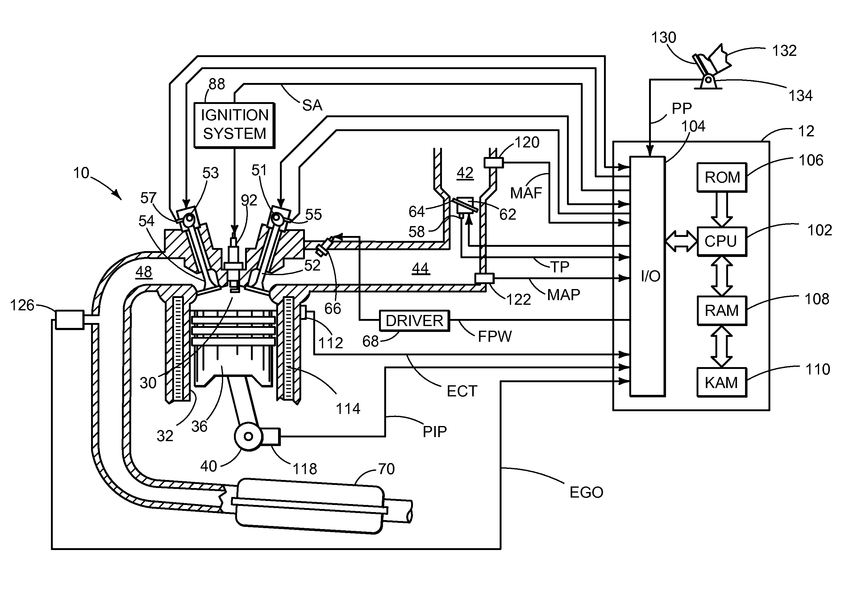
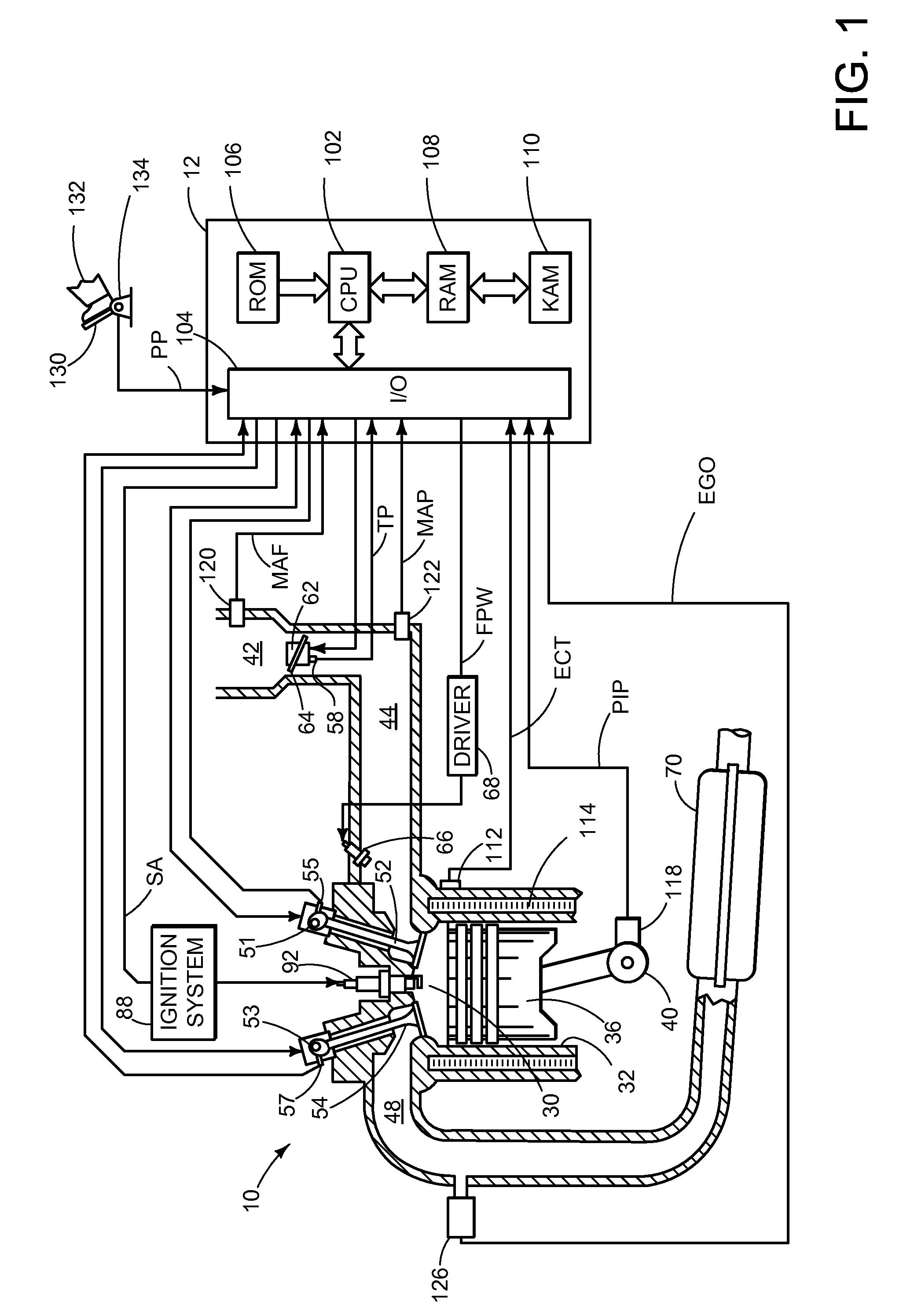
[0021]Referring to FIG. 1, internal combustion engine 10, comprising a plurality of cylinders, one cylinder of which is shown in FIG. 1, is controlled by electronic engine controller 12. Engine 10 includes combustion chamber 30 and cylinder walls 32 with piston 36 positioned therein and connected to crankshaft 40. Combustion chamber 30 is shown communicating with intake manifold 44 and exhaust manifold 48 via respective intake valve 52 and exhaust valve 54. Each intake and exhaust valve may be operated by an intake cam 51 and an exhaust cam 53. Alternatively, one or more of the intake and exhaust valves may be operated by an electromechanically controlled valve coil and armature assembly. The position of intake cam 51 may be determined by intake cam sensor 55. The position of exhaust cam 53 may be determined by exhaust cam sensor 57.

[0022]Intake manifold 44 is also shown intermediate of intake valve 52 and air intake zip tube 42. Fuel is delivered to fuel injector 66 by a fuel syste...


PUM


Abstract

A system for improving distribution of gases within an intake manifold of an engine is presented. The system may be used to improve engine air-fuel control. In one example, turbulence of gases entering an intake manifold is increased.

Description

FIELD[0001]The present description relates to a system for improving vapor distribution within an intake manifold of an engine. The system may be particularly useful for engines that have intake port runners with a bell mouth configuration.BACKGROUND AND SUMMARY[0002]An intake manifold of an engine may be configured to receive gases and provide vacuum to devices external the intake manifold. In one example, fuel vapors accumulated from a vehicle fuel system may be introduced to an intake manifold by way of a port. One system for distributing gases in an intake manifold is described in U.S. Pat. No. 7,299,787. This system provides for a gas introducing pipe that is upstream of a partitioning part, and the intake manifold is bifurcated by the part. Gases flowing from the gas introducing pipe are directed to a first or second group of cylinders by way of the partitioning plate.[0003]The above-mentioned method can also have several disadvantages. Specifically, the intake manifold limits...

Claims


Application Information

Patent Timeline
Patent Type & Authority Patents(United States)
IPC IPC(8): F02M35/10
CPCF02M35/10019F02M35/10045F02M35/10052F02M35/10111F02M35/10229F02M35/116
Inventor BORN, DAVIDDICKEY, NOLAN
Owner FORD GLOBAL TECH LLC
Why Eureka
Try Eureka