Device and system for lifting a motor vehicle

a technology for motor vehicles and systems, applied in the direction of lifting devices, lifting frames, trap doors, etc., can solve the problems of increasing the cost and complexity of installation, difficult or unfeasible to install hydraulically-powdered lifts in certain locations, and adding to the cost and complexity of installing and removing lifts

Active Publication Date: 2012-06-05
STERTIL
View PDF74 Cites 18 Cited by
  • Summary
  • Abstract
  • Description
  • Claims
  • Application Information

AI Technical Summary

Problems solved by technology

The need for a relatively deep trench or hole can increase the cost and complexity of the installation, and can make it difficult or unfeasible to install a hydraulically-powdered lift in certain locations, e.g., where the water table or bedrock level is relatively shallow.
Moreover, the structure required to support the casing is usually fixed and cast in concrete, with reinforcing bars, further adding to the cost and complexity associated with installing and removing the lift.
The need to route relatively large amounts of pressurized hydraulic fluid through an underground casing generates a potential for contamination of the surrounding area caused by leakage of the hydraulic fluid.
Moreover, the risk of ground contamination can be relatively high in applications wherein the unit that pressurizes and controls the flow of the hydraulic fluid is located within the trench or hole that accommodates the cylinder.

Method used


Image

  • Device and system for lifting a motor vehicle
  • Device and system for lifting a motor vehicle
  • Device and system for lifting a motor vehicle

Examples


Embodiment Construction

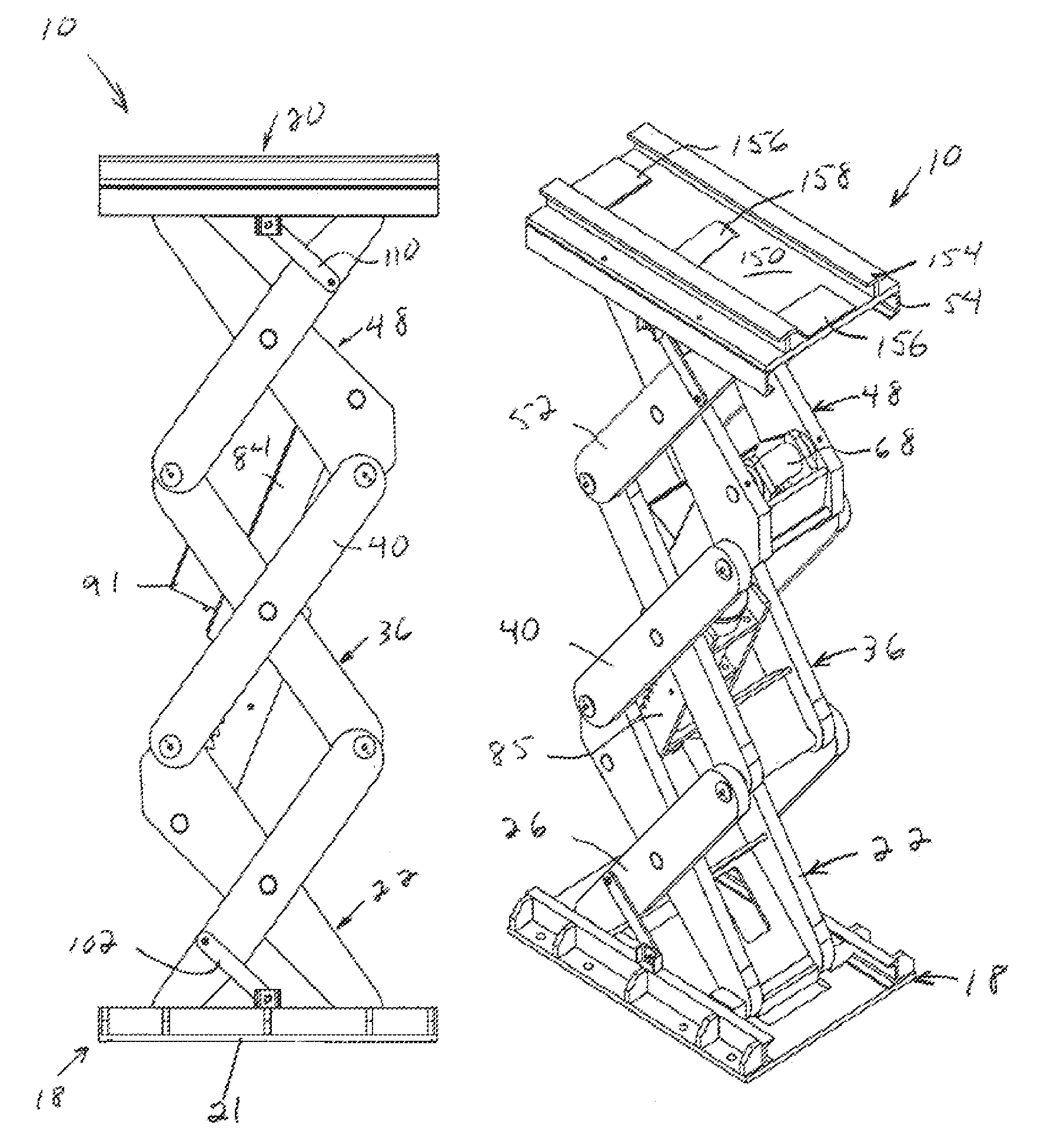
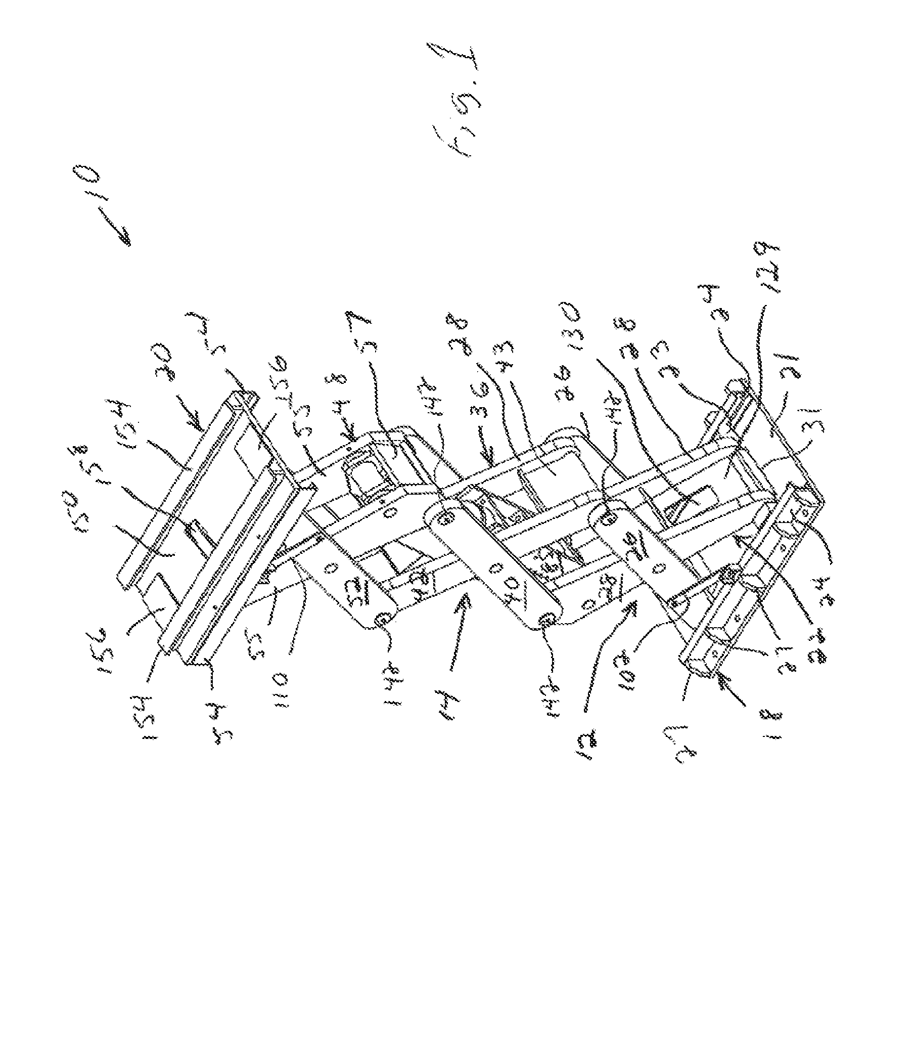
[0055]FIGS. 1-15 depict a preferred embodiment of a lifting device 10 in the form of a scissors jack, and various components thereof. The lifting device 10 can be used to lift a vehicle such as a bus 200, as shown in FIGS. 16-18. The lifting device 10 is believed to be particularly well suited for lifting relatively heavy vehicles such as the bus 200, due to the relatively high lifting capacity and relatively small size of the lifting device 10.

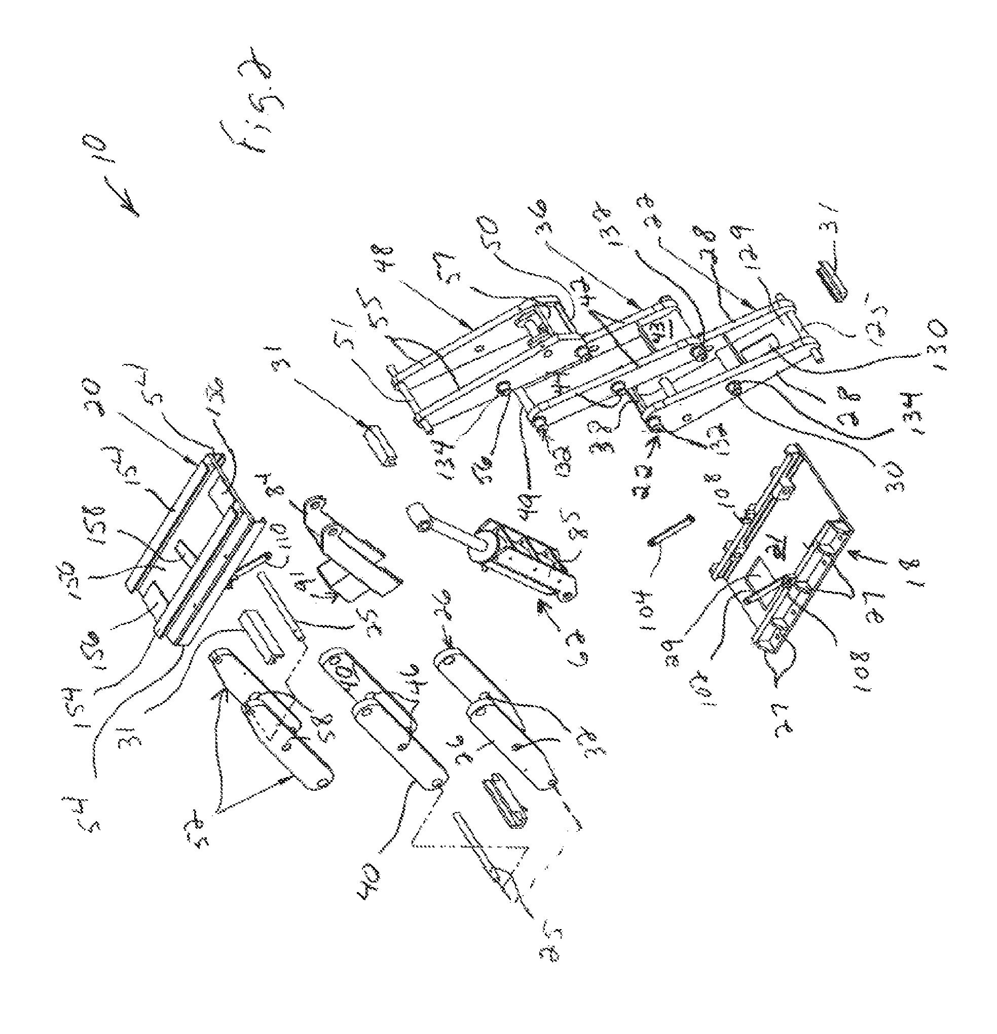
[0056]The lifting device 10 can move between an extended position (FIGS. 1 and 5A-6) and a retracted (collapsed) position (FIGS. 3A-4). The lifting device 10 comprises a first (bottom) tier 12, a second (intermediate) tier 14, and a third (upper) tier 16 (see FIG. 1). The lifting device also comprises a base 18 and a bolster 20.

[0057]The base 18 comprises a base plate 21, and two substantially C-shaped channels 24 secured to the base plate 21 by a suitable means such as welding. The base plate 21 can be formed from ¾-inch thick A36 mild steel...


PUM

PropertyMeasurementUnit
diameteraaaaaaaaaa
pressureaaaaaaaaaa
pressureaaaaaaaaaa

Abstract

A preferred embodiment of a system includes a lifting device for lifting a motor vehicle, a support structure for mounting the lifting device in a pit, and a carriage for supporting the lifting device from the support structure and being movable within the support structure. The system also includes a cover coupled to opposite sides of the carriage so that the cover extends away from the carriage and continuously between the opposite sides of the carriage.

Description

CROSS-REFERENCE TO RELATED APPLICATIONS[0001]This application is the National Stage of International Application No. PCT / US2005 / 017320, filed May 17, 2005, which claims the benefit of the filing date of U.S. Provisional Application No. 60 / 571,829, filed May 17, 2004, the disclosure of which is incorporated herein by reference in its entirety.FIELD OF THE INVENTION[0002]The present invention relates to devices and systems for lifting a motor vehicle, such a bus, to facilitate maintenance or service operations on the motor vehicle.BACKGROUND OF THE INVENTION[0003]Hydraulically-powered lifts are commonly used at maintenance facilities and service stations to lift buses, trucks, automobiles, and other types of motor vehicles. Lifting a motor vehicle is often necessary when performing service or maintenance operations such as tire or brake replacement, or tasks that require access to the underside of the motor vehicle.[0004]Conventional hydraulic lifts typically comprise a hydraulic cyli...

Claims


Application Information

Patent Timeline
Patent Type & Authority Patents(United States)
IPC IPC(8): B66F3/08
CPCB66B9/16B66F7/0666B66F7/28B66F7/08Y10T29/49947E06B5/01
Inventor POLINS, KURT EFELPEL, GLENN DPAVLICK, ALLAN
Owner STERTIL
Why Eureka
Try Eureka