Developing roller, manufacturing method thereof, developing apparatus and image forming apparatus
a technology of developing rollers and manufacturing methods, applied in the direction of instruments, applications, roads, etc., can solve the problems of low yield, insufficient charging and fog to occur, insufficient charging, etc., and achieve the effect of high reliability
- Summary
- Abstract
- Description
- Claims
- Application Information
AI Technical Summary
Benefits of technology
Problems solved by technology
Method used
Image
Examples
first embodiment
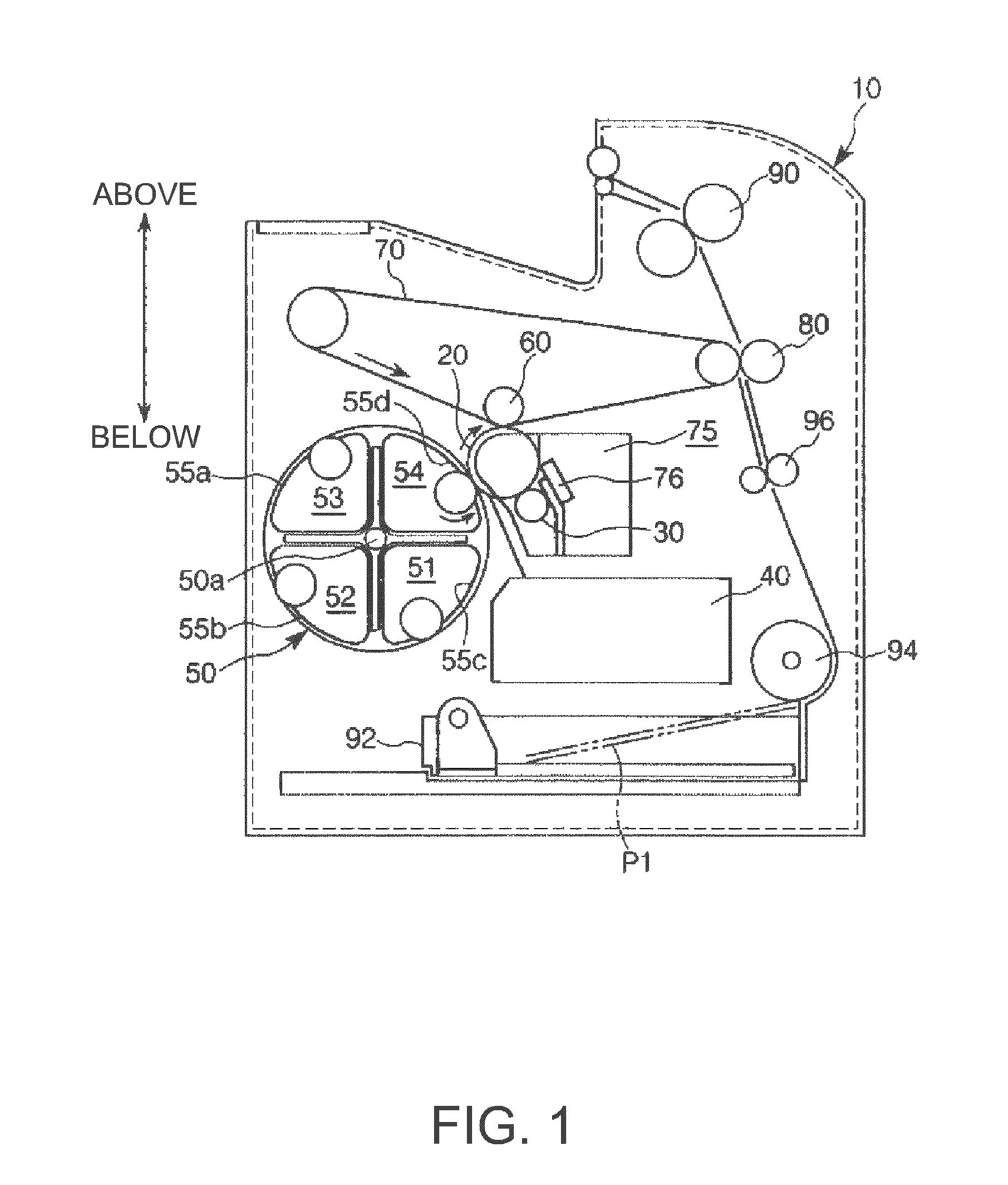
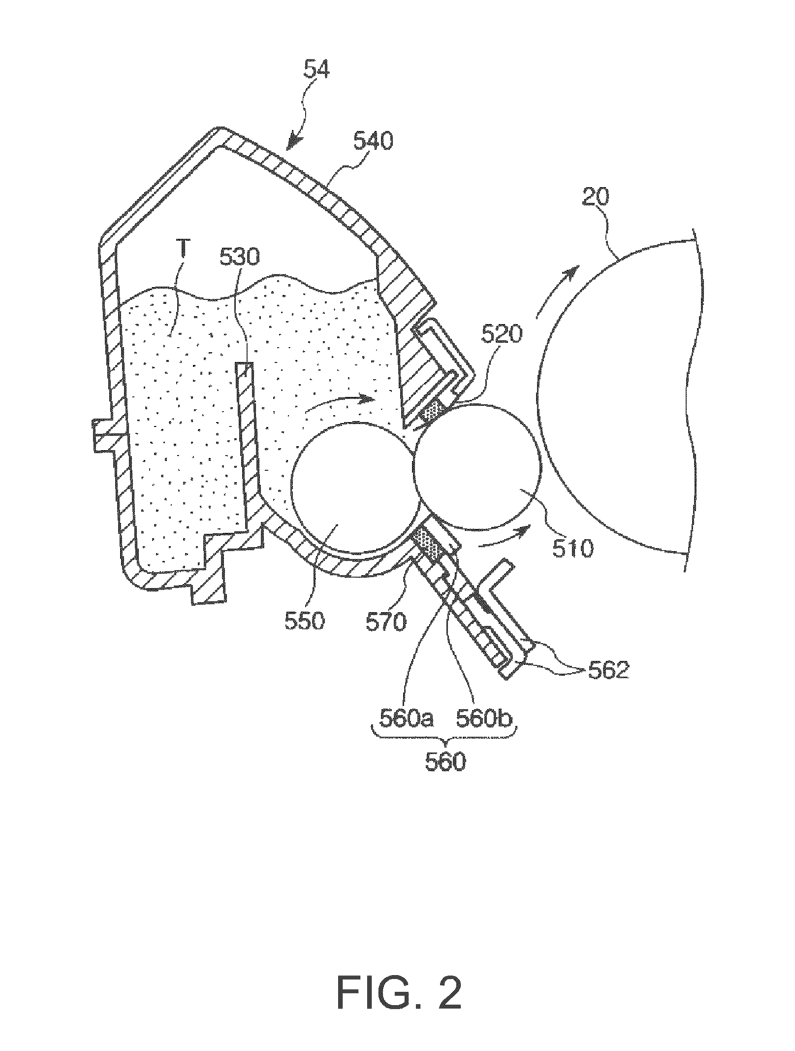
[0064]FIG. 1 is a schematic sectional view showing a schematic structure of an image forming apparatus in accordance with the invention, and FIG. 2 is a schematic sectional view showing a schematic structure of a developing apparatus in accordance with (a first embodiment of) the invention.
[0065]Note that hereinafter the upper side and the lower side in the figures will be referred to as “above” and “below”, respectively.
[0066]Image Forming Apparatus
[0067]Referring to FIG. 1, a laser-beam printer (hereinafter referred to only as a “printer”) 10 as an example of an image forming apparatus will be described.
[0068]As shown in FIG. 1, the printer 10 has a photosensitive member 20 that carries a latent image and rotates in the arrow direction in the figure.
[0069]Disposed along the rotation direction (clockwise) of the photosensitive member 20 are a charging unit 30, an exposure unit 40, a developing unit 50, a primary transfer unit 60 and an intermediate transfer member 70, and a cleanin...
second embodiment
[0403]FIG. 9 is an enlarged plan view of the groove 2 formed in the developing roller 510.
[0404]A second embodiment of the developing roller 510 of the invention will be described below with reference to this drawing.
[0405]Description will be given mainly on differences from the above embodiment, and explanation on the same elements as those of the above embodiment will be omitted.
[0406]This embodiment differs from the first embodiment in the shape of the protrusion portion 3 and the crossing angle between the first groove 21 and the second groove 22.
[0407]As shown in FIG. 9, the top surface 31 of the protrusion portion 3 is of a approximately planar, rhombic shape.
[0408]That is, the plurality of first grooves 21 and the plurality of second grooves 22 intersect each other, but do not intersect at right angles.
[0409]The angle θ in this case at which the first groove 21 and the second groove 22 intersect each other is preferably 20 to 135°, and more preferably 45 to 90°.
[0410]Setting ...
third embodiment
[0416]FIG. 10 is a plan view showing a schematic structure of the developing roller 510.
[0417]A third embodiment of the developing roller 510 of the invention will be described below with reference to this drawing.
[0418]Description will be given mainly on differences from the above embodiments, and explanation on the same elements as those of the above embodiments will be omitted.
[0419]This embodiment is the same as the first embodiment except that the surface roughness RO of the top surfaces 31 of the protrusion portions 3 partially varies along the longitudinal direction of the main body 300.
[0420]In other words, while the surface roughness RO of the top surface 31 of the protrusion portion 3 is the same for the whole of the groove formation section 320 in the first embodiment, the surface roughness RO of the top surface 31 located at an end portion 323 of the groove formation section 320 of the main body 300 is smaller than that of the top surface 31 located at a center portion 3...
PUM
| Property | Measurement | Unit |
|---|---|---|
| angle | aaaaa | aaaaa |
| diameter | aaaaa | aaaaa |
| diameter | aaaaa | aaaaa |
Abstract
Description
Claims
Application Information
 - R&D
- Intellectual Property
- Life Sciences
- Materials
- Tech Scout
- Unparalleled Data Quality
- Higher Quality Content
- 60% Fewer Hallucinations
Browse by: Latest US Patents, China's latest patents, Technical Efficacy Thesaurus, Application Domain, Technology Topic, Popular Technical Reports.
© 2025 PatSnap. All rights reserved.Legal|Privacy policy|Modern Slavery Act Transparency Statement|Sitemap|About US| Contact US: help@patsnap.com


