Sliding sheet for fixing devices, manufacturing method for same, fixing device, and image forming apparatus

a technology for fixing devices and sliding sheets, which is applied in the direction of electrographic processes, manufacturing tools, instruments, etc., can solve the problems of insufficient wear resistance, reduced friction, and inability to say that the sliding sheet of fig. 11 has enough wear resistance, and achieves low cost and stable shape.

Active Publication Date: 2012-06-05
KONICA MINOLTA BUSINESS TECH INC
View PDF12 Cites 13 Cited by
  • Summary
  • Abstract
  • Description
  • Claims
  • Application Information

AI Technical Summary

Benefits of technology

[0013]Accordingly, an object of the present invention is to provide a sliding sheet for fixing devices which can maintain a stable shape and which can be manufactured at a low cost and a manufacturing method for the same.
[0018]The above described sliding sheet repeatedly has a thick section and a thin section substantially corresponding to positions on the sheet surface at least with respect to the sliding direction of the endless belt. Therefore, unlike the sliding sheets disclosed in JP 2005-3969 A and JP 2003-107936 A, the above sliding sheet does not return to its original flat shape even in the state of being exposed to heat and pressure for fixing operation, and so the shape of the sliding sheet is maintained stable. With the difference in thickness between the thick section and the thin thickness, high slidability against the endless belt is maintained. This makes it possible to maintain fixing quality. Moreover, the sliding sheet is formed only by locally changing the thickness of a single resin. Therefore, the sliding sheet may be manufactured at a low cost.
[0025]According to the manufacturing method for the sliding sheet, the sliding sheet can be manufactured at a low cost with use of a sheet material made of a single resin having a fixed thickness.
[0026]The sheet material should preferably be obtained by skiving (shaving) compression-molded resin. In that case, the sheet material is superior in wear resistance to the resin which is not compressed.
[0032]In this fixing device, the sliding sheet can maintain a stable shape, so that high slidability against the endless belt can be maintained with the difference in thickness between the thick section and the thin section. This makes it possible to maintain fixing quality. Moreover, the sliding sheet is formed only by locally changing the thickness of a single resin and therefore can be manufactured at a low cost. Therefore, the fixing device may also be manufactured at a low cost.

Problems solved by technology

Since the sliding sheet has a sliding surface 907S with unevenness which reflects the unevenness of the glass cloth 908, the unevenness retains the oil fed to the inner surface of the endless belt and thereby reduces the friction of the sliding sheet with the inner surface of the endless belt (if the sliding surface is flat, the oil is pushed out from a region equivalent to the nip section with pressure, resulting in failure in sufficient reduction of the friction).
However, it cannot be said that the sliding sheet of FIG. 11 has enough wear resistance.
More specifically, the sliding sheet of FIG. 11 has a problem that not only the sliding surface 907S is abraded away and flattened to cause increase in coefficient of friction but also worn powder generated by abrasion is mixed into oil so that apparent viscosity of the oil is increased, resulting in torque increase.
However, the sliding sheet of FIG. 12 has a disadvantage that the process for laminating and bonding the PTFE sheet 807 onto the glass cloth 808 is expensive and causes cost increase.
However, in the methods for gaining unevenness by pressing patterns such as embossing or by pressing sharp objects, the unevenness is eventually lost due to heat and pressure of the nip section.
Accordingly, the coefficient of friction may increase, and this may cause a problem that the fixing quality cannot be maintained.
In the method disclosed in JP 2002-299007 A, the glass is higher in coefficient of friction than the fluororesin, which may cause a problem of torque increase during start-up i.e., during the time when oil does not yet fully sit on the sliding surface of the sliding sheet.

Method used


Image

  • Sliding sheet for fixing devices, manufacturing method for same, fixing device, and image forming apparatus
  • Sliding sheet for fixing devices, manufacturing method for same, fixing device, and image forming apparatus
  • Sliding sheet for fixing devices, manufacturing method for same, fixing device, and image forming apparatus

Examples


Embodiment Construction

[0052]Hereinbelow, the present invention will be described in details in conjunction with the embodiments with reference to the drawings.

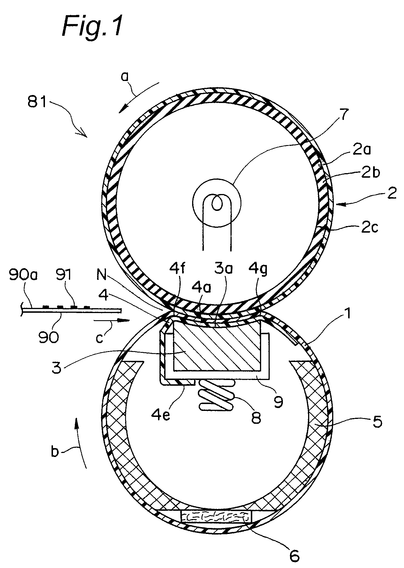
[0053]FIG. 1 shows a cross sectional configuration of a fixing device 81 having a sliding sheet 4 in one embodiment of the present invention, and FIG. 13 shows a schematic configuration of an electrophotographic color printer IMG as one example of an image forming apparatus incorporating the fixing device 81.

[0054]The color printer IMG has a photoconductor drum 60 generally in the center of a casing which is rotated clockwise in this example. Provided around the photoconductor drum 60 are an unshown charging section for uniformly charging the photoconductor drum surface, an exposure section 61 for exposing the photoconductor drum surface which is uniformly charged to form a latent image thereon, a developing section 62 for attaching toner of respective colors, cyan (C), magenta (M), yellow (Y) and black (K), to the photoconductor drum surface with ...


PUM

PropertyMeasurementUnit
pressureaaaaaaaaaa
areaaaaaaaaaaa
lattice pointsaaaaaaaaaa

Abstract

A sliding sheet for fixing devices in the present invention is inserted in between an endless belt constituting one member out of two members which form a nip section for fixing operation and a pressure member for pressing the endless belt from an inner surface side toward the other member out of the two members. The sliding sheet, which is made of a single resin, repeatedly has a thick section and a thin section at least with respect to a sliding direction of the endless belt due to substantial difference in resin amount per unit area corresponding to positions within a sheet surface.

Description

[0001]This application is based on an application No. 2007-179675 filed in Japan, the contents of which are hereby incorporated by reference.BACKGROUND OF THE INVENTION[0002]The present invention relates to a sliding sheet for fixing devices and a manufacturing method for the same. More specifically, the present invention relates to a sliding sheet inserted in between an endless belt constituting one member out of two members which form a nip section for fixing operation and a pressure member for pressing the endless belt from an inner surface side toward the other member out of the two members, and to a manufacturing method for the same.[0003]The present invention also relates to a fixing device having such a sliding sheet and to an image forming apparatus having the fixing device.[0004]General fixing devices include one having a sheet (referred to as a “sliding sheet”) inserted in between an endless belt constituting one member out of two members which form a nip section for fixin...

Claims


Application Information

Patent Timeline
Patent Type & Authority Patents(United States)
IPC IPC(8): G03G15/20
CPCG03G15/2053Y10T29/49826G03G2215/2035G03G2215/2009
Inventor OKUNO, JINJU
Owner KONICA MINOLTA BUSINESS TECH INC
Why Eureka
Try Eureka