

Heat flow measurement tool for a rack mounted assembly of electronic equipment
a technology of electronic equipment and measurement tools, which is applied in the direction of instruments, material heat development, electrical apparatus casings/cabinets/drawers, etc., can solve the problems of increasing the concentration of power and the requirement to dissipate heat from a given space, increasing the number of devices at the rack level, and reducing the air resistance. , the effect of reducing the air resistan
- Summary
- Abstract
- Description
- Claims
- Application Information
AI Technical Summary
Benefits of technology
Problems solved by technology
Method used
Image

Examples
Embodiment Construction
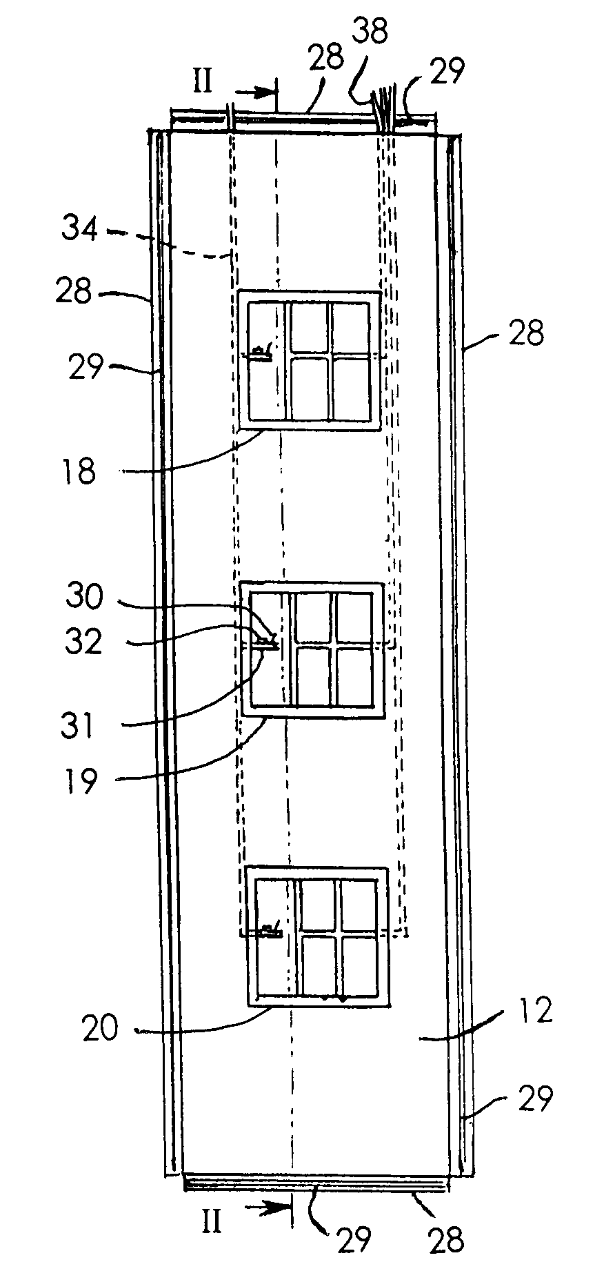
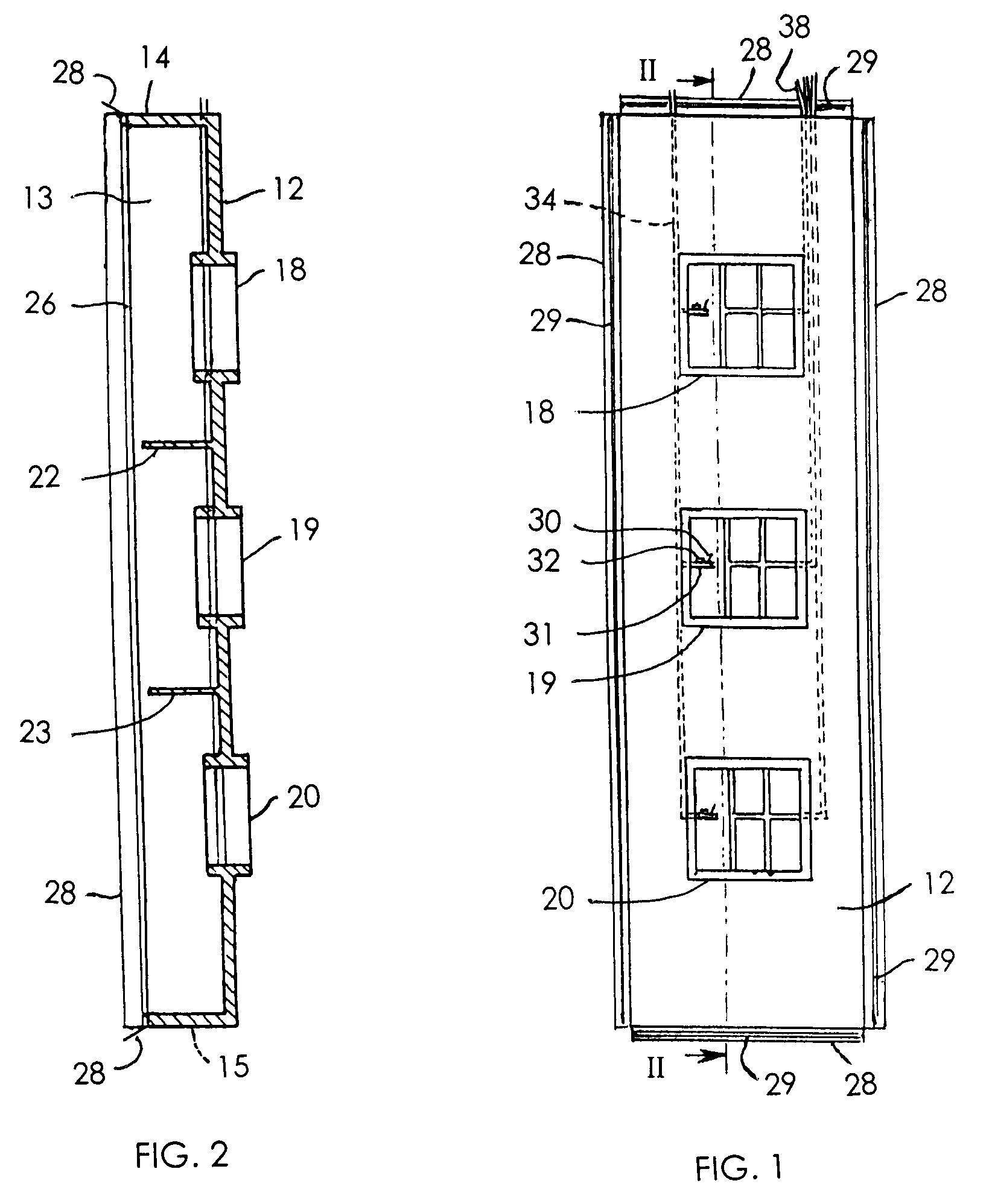
[0020]FIG. 1 illustrates the rear duct assembly 10 of the present invention and FIG. 2 is a section view of the rear duct assembly of FIG. 1 taken along line II-II. The duct assembly 10 includes an end wall 12 with contiguous side walls 13, top wall 14 and bottom wall 15. The end wall 12 includes integral upper, middle and lower duct portions 18, 19 and 20 respectively. Also formed integral with the end wall 12 and side walls 13 are a pair of flow partitioners 22 and 23 which are horizontal panels that divide the air passing through the assembly 10 into upper, middle and lower flow paths. The duct assembly, as illustrated, is formed of a closed cell plastic material, but could be constructed of any material that would confine and direct the air flow while possessing a low specific heat to enable the temperature of air passing through the assembly to quickly stabilize to the temperatures at the entry and exit of the system. For example, the assembly could be a flexible material forme...
PUM
| Property | Measurement | Unit |
|---|---|---|
| temperature | aaaaa | aaaaa |
| height | aaaaa | aaaaa |
| pressure | aaaaa | aaaaa |
Abstract
Description
Claims
Application Information