Hollow electrode with film for electrodeposition coating

a technology of coating and hollow electrode, which is applied in the field of hollow electrode, can solve the problems of remelting of coating film, and achieving excellent economic efficiency, easy handling, and reducing the number of components

Inactive Publication Date: 2012-06-12
OSAKA SODA CO LTD +1
View PDF12 Cites 0 Cited by
  • Summary
  • Abstract
  • Description
  • Claims
  • Application Information

AI Technical Summary

Benefits of technology

[0026]Since the electrode main body serves as a support of the barrier membrane and the barrier membrane is directly attached to the exterior surface of the electrode main body, the hollow electrode with a membrane for electrodeposition coating according to the present invention is small and lightweight and is more easily handled as compared to an electrode having a double structure in which a barrier membrane is arranged outside of the electrode at intervals. Further, there is no need for a specialized support for the barrier member so that the number of components is reduced and therefore the hollow electrode is excellent in economic efficiency. From the viewpoint of the original function to solve various problems caused by an increased concentration of an electrolyte, the performance of the hollow electrode is comparable to that of an electrode having a double structure.
[0027]Further, by firmly attaching the barrier membrane to the exterior surface of the electrode main body by an anchor effect or the like, it is possible to suppress the extension of the barrier membrane in the longitudinal direction due to swelling and to suppress the occurrence of wrinkles. Therefore, it is possible to suppress the occurrence of retaining paint which is a cause of defective electrodeposition coating.
[0028]Further, by using an insoluble electrode as the electrode main body, it is possible to avoid the elusion of electrode materials into a paint solution and an electrode solution, thereby reducing the contaminations of the barrier membrane and the electrode solution. Further, the insoluble electrode can have a higher current density as compared to a stainless steel electrode, and therefore it is possible to reduce the time required for coating and the number of electrodes.

Problems solved by technology

As a result, the concentration of amine, acetic acid or the like as an electrolyte (electrode solution) in the paint solution is increased so that there is a fear that problems such as remelting of a coating film and the occurrence of pinholes arise.
However, on the other hand, since the electrode device disclosed in Patent Documents 1 and 2 has a double structure in which the barrier membrane and the barrier membrane supporting member are arranged outside the tubular electrode at intervals, it is impossible to avoid the size of the electrode device becoming larger compared to that of the tubular electrode which is an electrode main body.
Further, since the electrode device needs the barrier membrane and the barrier membrane supporting member in addition to the tubular electrode which is an electrode main body, the number of components is increased, thereby making it impossible to avoid an increase in production cost.
Further, as another problem, there is a case where the barrier membrane, such as an ion exchange membrane, arranged outside the tubular electrode at intervals swells or extends in use.
For this reason, there is a problem that wrinkles occur in the barrier membrane or it is impossible to firmly fix the barrier membrane to suppress the occurrence of wrinkles.
It was a problem that the occurrence of wrinkles in the barrier membrane is a cause of retaining of a resin component contained in a paint solution in the wrinkles, which further causes coating defects such as pits and lumps.
As a result, it caused a problem that the electrode solution and an ion exchange membrane are contaminated or it is difficult to reuse the electrode solution.
On the other hand, a ferrite electrode is brittle and therefore there was a problem that careful handling was required.

Method used


Image

  • Hollow electrode with film for electrodeposition coating
  • Hollow electrode with film for electrodeposition coating

Examples


example

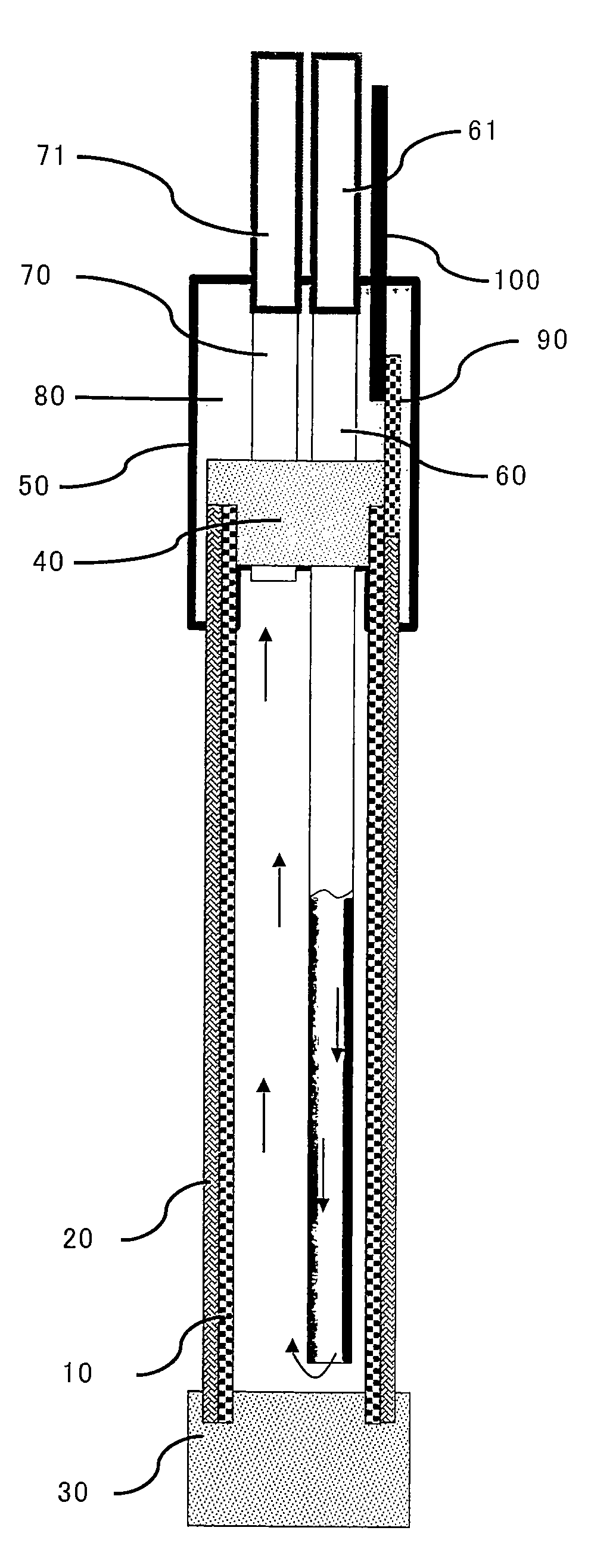
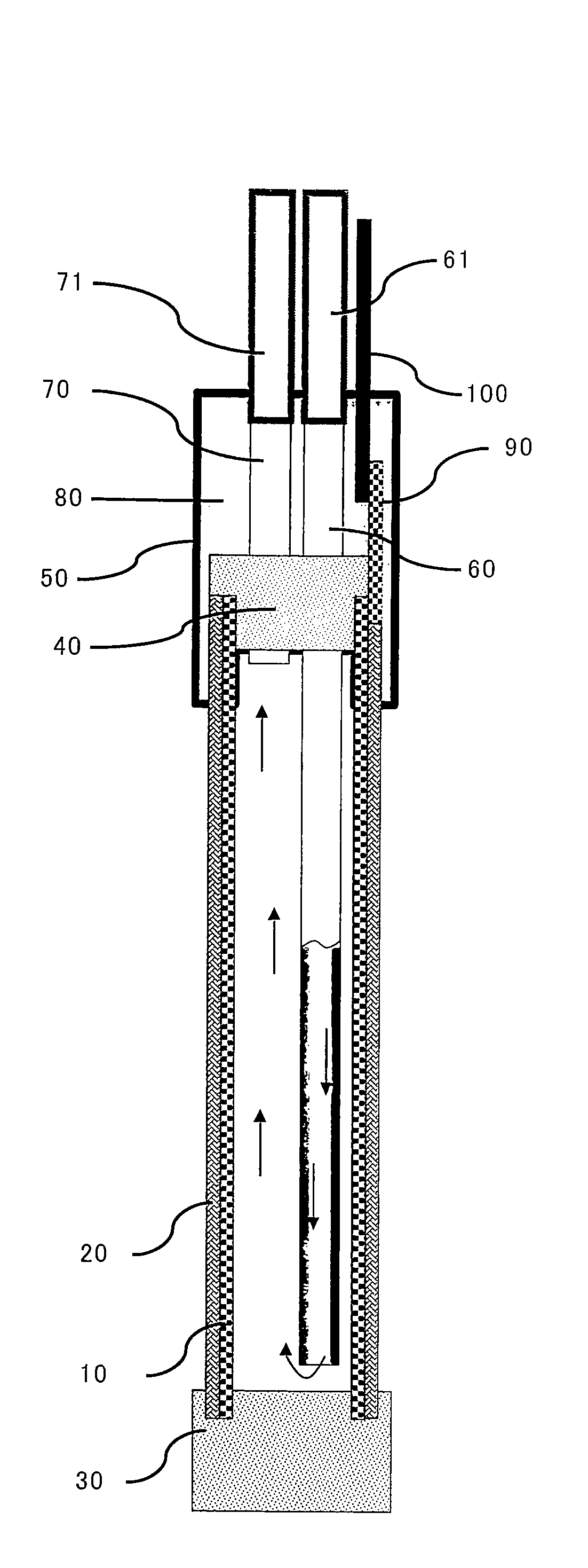
[0043]Finally, a hollow electrode with a membrane for electrodeposition coating according to the present invention was actually produced. A result of conducting a performance test will be described. The hollow electrode produced has a structure shown in FIG. 1.

[0044]On a titanium plate having a width of 100 mm, a length of 2540 mm, and a thickness of 1 mm, a large number of rhombic openings regularly arranged each having a LW of 6 mm and a SW of 3 mm were formed by punching. One surface of the punched metal was coated with an electrode active material, and this coating process was repeated five times.

[0045]More specifically, first a titanium plate as a raw material was washed to degrease, and then the entire surface of the titanium plate was subjected to blast treatment using #30 Alundum at a pressure of 0.4 MPa for about 10 minutes. The treated plate was washed in running water all day long, and was then dried. An electrode active material coating liquid having a liquid composition...


PUM

PropertyMeasurementUnit
thicknessaaaaaaaaaa
thicknessaaaaaaaaaa
thicknessaaaaaaaaaa

Abstract

In order to solve various problems such as a reduction in a paint resin with the progress of electrodeposition coating treatment and remelting of a coating film or the occurrence of pinholes caused by an increased concentration of an electrolyte as a result of the reduction, upsizing of a hollow electrode with a membrane for electrodeposition coating combined with a barrier membrane (e.g., an ion exchange membrane) and an increase in the number of components should be avoided. In order to realize this, a barrier membrane 20 such as an ion exchange membrane is attached to the exterior surface of an electrode main body 10, which is in a hollow state made of a conductive material and configured so as to allow a liquid to pass through freely between the inside and outside of the electrode serving as a support.

Description

TECHNICAL FIELD[0001]The present invention relates to a hollow electrode for use in electrodeposition coating for electrically coating with an electrically-charged paint. More specifically, the present invention relates to a hollow electrode with a membrane for electrodeposition coating combined with a barrier membrane (e.g., an ion exchange membrane), in order to solve various problems such as a reduction in a paint resin with the progress of electrodeposition coating treatment and remelting of a coating film and the occurrence of pinholes caused by an increased concentration of an electrolyte as a result of the reduction.BACKGROUND ART[0002]In electrodeposition coating, as is well known, electrodes are placed in an electrodeposition bath filled with a paint solution. Usually, the electrodes are arranged on both sides of the electrodeposition bath. Then, an object to be coated which is moved between the electrodes arranged in the electrodeposition bath serves as a counter electrode...

Claims


Application Information

Patent Timeline
Patent Type & Authority Patents(United States)
IPC IPC(8): C25B9/10C25B9/23
CPCC25D13/22C25D17/12C25D13/00
Inventor MATSUI, SHOUHEIYOSHIDA, YASUSHISHOJI, NOBUYOSHIMATSUMURA, YUKIO
Owner OSAKA SODA CO LTD
Why Eureka
Try Eureka