Electrostatic chuck and substrate temperature adjusting-fixing device

a technology of temperature adjustment and fixing device, which is applied in the direction of electrets, electrical devices, electrostatic charges, etc., can solve the problems of high voltage, easy attachment of particles to the opposite surface, and inability to obtain sufficient adsorption for

Active Publication Date: 2012-06-12
SHINKO ELECTRIC IND CO LTD
View PDF13 Cites 76 Cited by
  • Summary
  • Abstract
  • Description
  • Claims
  • Application Information

AI Technical Summary

Benefits of technology

[0041]According to the invention, it is possible to provide an electrostatic chuck capable of reducing particles attached to an opposite surface of an adsorption object held by the electrostatic chuck in an adsorption state and a substrate temperature adjusting-fixing device having the electrostatic chuck.

Problems solved by technology

However, an application of a high voltage is required and a sufficient adsorption force cannot be obtained when a contact area between the electrostatic chuck and the substrate is not large.
However, in the substrate temperature adjusting-fixing device 100 according to the conventional art, since the contact area between the substrate 107 and the upper surfaces of the plurality of protrusion portions 102c and the outer peripheral seal ring 102b is large, a problem arises in that particles are easily attached to an opposite surface of the substrate 107 contacting with the upper surfaces of the plurality of protrusion portions 102c and the outer peripheral seal ring 102b.
As a result, it is not possible to solve the problem that the particles are easily attached to the opposite surface of the substrate 107 just by making the diameter φ1 of the upper surface of the plurality of protrusion portions 102c as small as possible.

Method used


Image

  • Electrostatic chuck and substrate temperature adjusting-fixing device
  • Electrostatic chuck and substrate temperature adjusting-fixing device
  • Electrostatic chuck and substrate temperature adjusting-fixing device

Examples


Embodiment Construction

[0050]Hereinafter, an exemplary embodiment of the invention will be described with reference to the accompanying drawings.

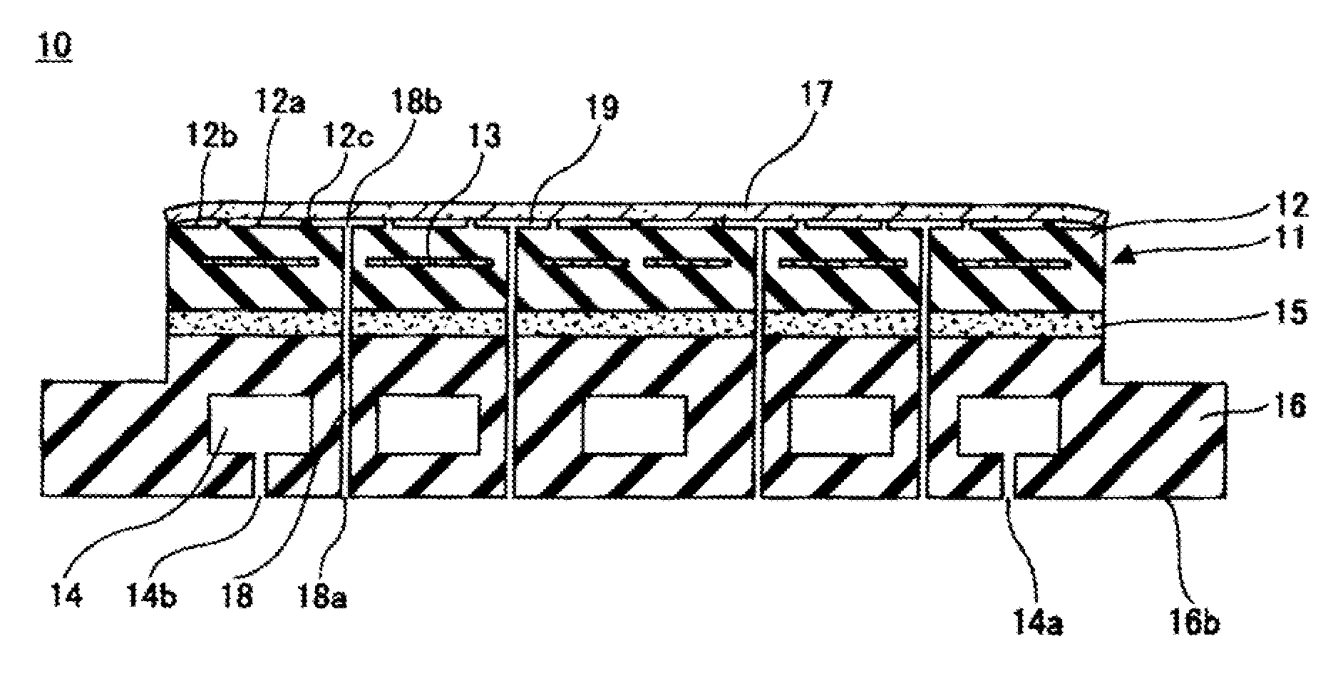
[0051]FIG. 4 is a top vies simply showing a substrate temperature adjusting-fixing device 10 according to the invention. FIG. 5 is a cross sectional view simply showing the substrate temperature adjusting-fixing device 10 according to the invention when taken along the line B-B shown in FIG. 4. As shown in FIGS. 4 and 5, the substrate temperature adjusting-fixing device 10 includes an electrostatic chuck 11, an adhesive layer 15, and a base plate 16.

[0052]The electrostatic chuck 11 is a coulombic-force electrostatic chuck having a base body 12 and an electrostatic electrode 13. The base body 12 is a dielectric and is fixed onto the base plate 16 via the adhesive layer 15. As the base body 12, for example, ceramic or the like may be used, but all materials may be used so long as the dielectric may have a plurality of protrusion portions 12c described below. A thic...


PUM


Abstract

There is provided an electrostatic chuck for placing an adsorption object or a base body having an electrostatic electrode embedded therein and generating a coulombic force between the adsorption object and the electrostatic electrode by applying a voltage to the electrostatic electrode so as to hold the adsorption object in an adsorption state, wherein the base body includes a upper surface of the base body opposed to the adsorption object and a protrusion portion provided in the upper surface of the base body so as to come into contact with the adsorption object, and wherein the protrusion portion is provided in a region except for an outer edge portion of the upper surface of the base body, and the outer edge portion is substantially formed in the same plane as that of the upper surface of the base body.

Description

BACKGROUND OF THE INVENTION[0001]The present invention relates to an electrostatic chuck and a substrate temperature adjusting-fixing device, and more particularly, to an electrostatic chuck for adsorbing an adsorption object placed on a base body and a substrate temperature adjusting-fixing device.[0002]In the past, a coating device (for example, a CVD device, a PVD device, and the like) or a plasma etching device used to manufacture a semiconductor unit such as an IC or an LSI has a stage for holding a substrate within a vacuum treatment chamber with high precision. As such a stage, for example, a substrate temperature adjusting-fixing device having an electrostatic chuck is proposed.[0003]The substrate temperature adjusting-fixing device holds the substrate in an adsorption state by using the electrostatic chuck and controls a temperature of the substrate held in an adsorption state to be a predetermined temperature. An example of the electrostatic chuck includes a coulombic-forc...

Claims


Application Information

Patent Timeline
Patent Type & Authority Patents(United States)
IPC IPC(8): H01L21/683H01T23/00H01G7/02H05F3/00
CPCH01L21/6831H01L21/687
Inventor KOYAMA, TOMOAKITAMAGAWA, KOKI
Owner SHINKO ELECTRIC IND CO LTD
Why Eureka
Try Eureka