Gas system for an automatic firearm

a technology of automatic firearms and gas systems, applied in the field of gas systems, can solve the problems of reducing both inherent accuracy and detraction of the system, increasing off-axis forces, etc., and achieve the effect of clean and efficient operation

Active Publication Date: 2012-06-19
MAGPUL INDUSTRIES
View PDF10 Cites 16 Cited by
  • Summary
  • Abstract
  • Description
  • Claims
  • Application Information

AI Technical Summary

Benefits of technology

[0013]In view of the foregoing disadvantages inherent in the known types of gas systems, this invention provides an improved gas system for a firearm. As such, the present invention's general purpose is to provide a new and improved gas system that is both clean and efficient in operation and encumbrance.

Problems solved by technology

However, detractions of this system are evident since the piston is located in a forward position and must be linked via a long operating rod to the firearm mechanism.
This increases muzzle weight (which is already heavily affected by modern rail-mounted accessories), increases off-axis forces which can reduce both inherent accuracy due to barrel flex and user accuracy due to muzzle rise or other induced moments.
There is also an inherent instability caused by the imbalance of the system.
However, direct impingement introduces an excessive amount of un-burnt powder residue and combustion by-products into the core operating mechanism of the weapon such as the fire-control group.
While other operating systems exist that mount the piston in close proximity to the receiver, this hybrid system is different than others such as the Benelli ARGO system for the M1018 and M4 Super 90 shotguns which tap the gas closer to the chamber and would not be suitable for a rifle.

Method used


Image

  • Gas system for an automatic firearm
  • Gas system for an automatic firearm
  • Gas system for an automatic firearm

Examples


Embodiment Construction

[0038]With reference now to the drawings, the preferred embodiment of the gas system is herein described. It should be noted that the articles “a”, “an”, and “the”, as used in this specification, include plural referents unless the content clearly dictates otherwise.

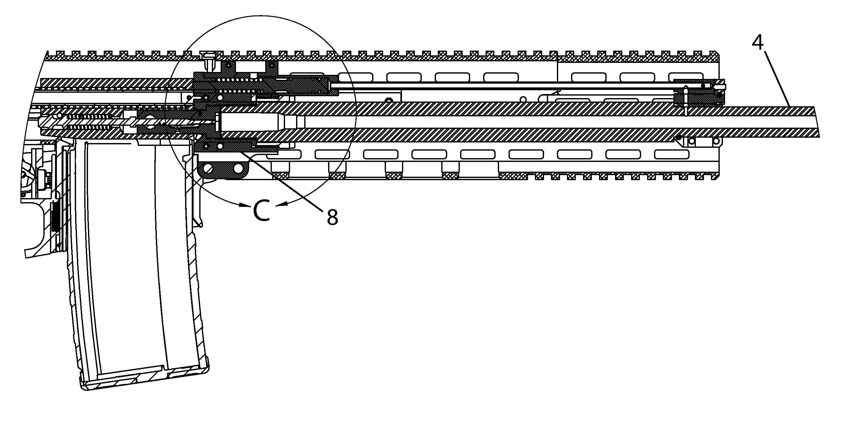
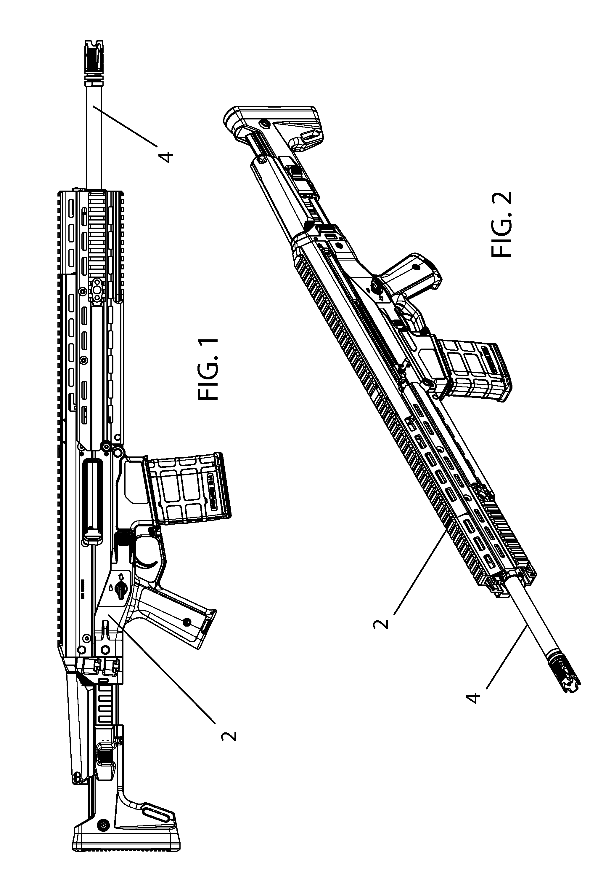
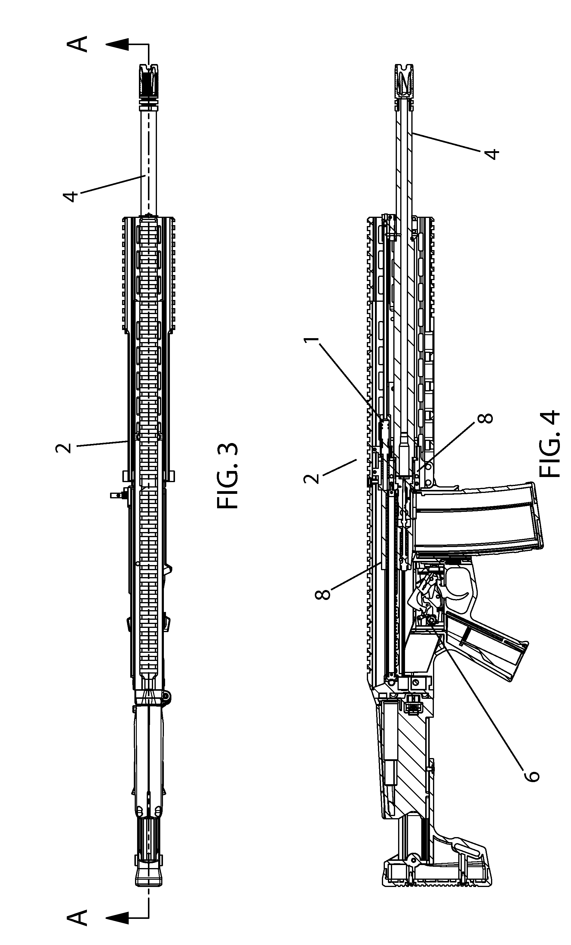
[0039]With reference to the FIGS. 1-3, the system 1 resides in a firearm 2, generally above the barrel 4. The system itself comprises a gas tube 10 extending parallel to the barrel 4 of a firearm and is best shown in FIGS. 4-8. The head of the tube 10 resides in gas manifold 12 towards the forward of the barrel 4. Gas manifold 12 taps into barrel 4 to divert gasses from firing into the system. A gas block 16 surrounds the tap 14 and gas manifold 12 to better seal the system 1. At the rear of gas tube 10 is the piston assembly, comprising of piston 18, piston housing 20 coaxial to the piston 18, and sealing bushing 24. Sealing bushing 24 may be of one piece with the piston housing 20. Piston housing 20 is mounted on the t...


PUM


Abstract

The present invention is a gas system for a firearm comprising a hollow gas tube extending between a forward gas tap in a firearm's barrel and a rearward piston assembly to impinge upon and operate the firearm's bolt operating system. The system does not have a translation rod extending between the two components as in prior art systems nor does it have a rearward tap like others. As such, it balances cleanliness and weight reduction of the prior art systems and reduces moving parts.

Description

CROSS-REFERENCES TO RELATED APPLICATIONS[0001]This application claims priority as a non-provisional perfection of prior filed U.S. Provisional Application No. 61 / 147,425, filed Jan. 26, 2009 and incorporates the same herein by reference in its entirety.FIELD OF THE INVENTION[0002]The present invention relates to the field of firearms and more particularly relates to a gas system for operating a bolt operation system in a firearm.BACKGROUND OF THE INVENTION[0003]Automatically-powered gas-operating mechanisms for firearms are well known in the prior art. These systems allow for the extraction, ejection, and loading operations to be performed automatically by tapping into the energetic gases generated by the chemical reaction of the propellants used to accelerate the projectile.[0004]These systems typically tap into the barrel to vent a portion of the gas used to propel the bullet and divert that gas flow to impinge on a piston which drives the mechanism. Traditional systems use a shor...

Claims


Application Information

Patent Timeline
Patent Type & Authority Patents(United States)
IPC IPC(8): F41A5/18
CPCF41A5/28
Inventor JUAREZ, JUSTIN
Owner MAGPUL INDUSTRIES
Why Eureka
Try Eureka