Lubrication system and method, and vortex flow separator for use therewith

a technology of vortex flow and lubrication system, which is applied in the direction of engine lubrication, moving filter element filter, sediment separation by centrifugal force, etc., can solve the problems of aircraft design not being well suited to receive separators inside the oil tank, affecting the lubrication of components of the engine, and affecting the lubrication effect of the engin

Active Publication Date: 2012-06-19
PRATT & WHITNEY CANADA CORP
View PDF20 Cites 19 Cited by
  • Summary
  • Abstract
  • Description
  • Claims
  • Application Information

AI Technical Summary

Problems solved by technology

One drawback of such a system is that the supply of make-up oil can be disturbed when there are pressure variations in the scavenge oil pump line, for instance.
For example, some aircraft designs are not well suited to receive a separator inside the oil tank, and it can be desired to position the separator elsewhere.
Furthermore, chips, foreign particles, or debris can be a sign of engine wear, and their recirculation to the engine is typically undesirable.
Known separators were not appropriately designed to collect and / or detect them.

Method used


Image

  • Lubrication system and method, and vortex flow separator for use therewith
  • Lubrication system and method, and vortex flow separator for use therewith
  • Lubrication system and method, and vortex flow separator for use therewith

Examples


Embodiment Construction

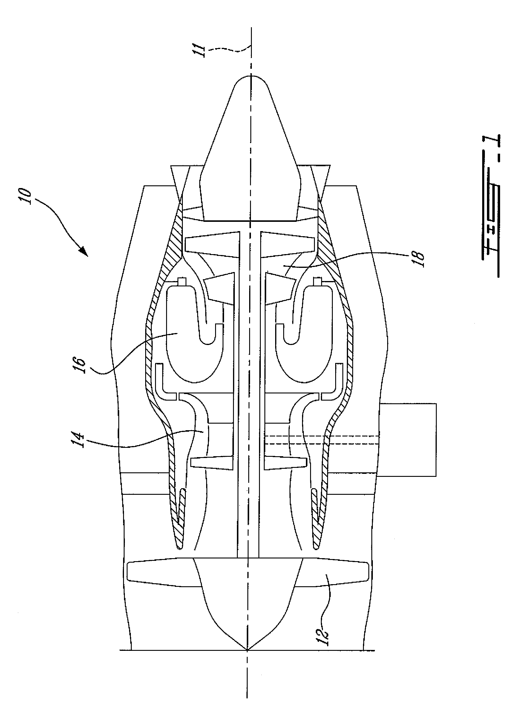
[0018]FIG. 1 illustrates a gas turbine engine 10 of a type preferably provided for use in subsonic flight, generally comprising in serial flow communication a fan 12 through which ambient air is propelled, a multistage compressor 14 for pressurizing the air, a combustor 16 in which the compressed air is mixed with fuel and ignited for generating an annular stream of hot combustion gases, and a turbine section 18 for extracting energy from the combustion gases.

[0019]Several components of the gas turbine engine 10 require lubrication, such as bearings for the turbine section 18 and the multistage compressor 14, for instance.

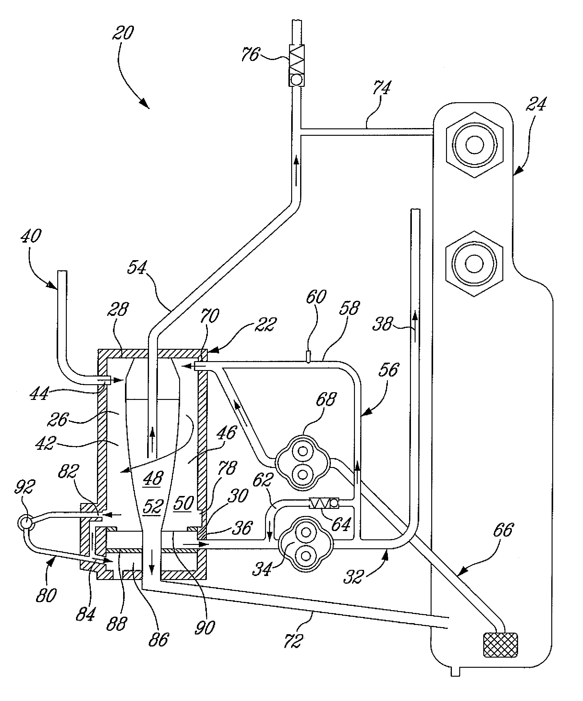
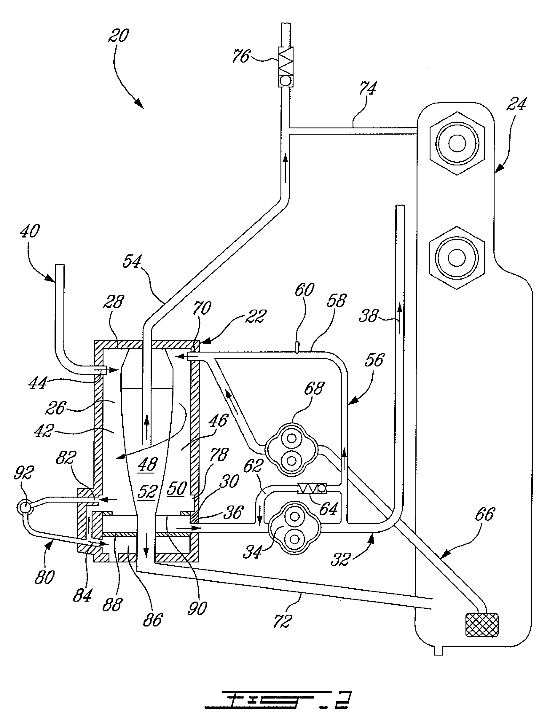
[0020]FIG. 2 illustrates an example of an oil system 20 that can be used to convey oil to and from the engine 10. The oil system 20 generally includes a vortex flow separator 22, and an oil reserve, or tank 24. The separator 22 has a generally cylindrical vortex chamber 26 having an inlet end 28 and an outlet end 30. A first pump line 32 having a first pump 34 is p...


PUM

PropertyMeasurementUnit
areaaaaaaaaaaa
flow rateaaaaaaaaaa
pressureaaaaaaaaaa

Abstract

An aircraft engine lubrication system has a vortex separator, a first pump line having a first pump, an inlet connected to a separated lubricant area at the outlet end of the separator, and an outlet connectable to the engine. A scavenge line is provided for returning lubricant from the engine to an inlet end of the separator. A lubricant tank is connected in fluid flow communication with the separator by a connection line. A second pump line having a second pump has an inlet connected to the lubricant tank and an outlet connected to the separator for pumping lubricant from the tank to the inlet end of the separator.

Description

TECHNICAL FIELD[0001]The invention relates generally to lubrication systems and methods used to convey lubricant to and from lubricated components of an engine and, more particularly, to an improved system and method for lubricating components of an aircraft engine.BACKGROUND OF THE ART[0002]It is known to use vortex flow separator in aircraft engines. Such systems have the advantage of being substantially unaffected by changes in the gravity force caused by knife-edge or inverted flight, for example. The vortex flow separator is typically positioned inside the oil tank, and make-up oil can make its way from the oil tank to the separator through a plurality of make-up lines, and be entrained into the main circuit by the kinetic energy of the flow of scavenge oil. One drawback of such a system is that the supply of make-up oil can be disturbed when there are pressure variations in the scavenge oil pump line, for instance.[0003]Although previously known separators and oil systems were...

Claims


Application Information

Patent Timeline
Patent Type & Authority Patents(United States)
IPC IPC(8): F01M1/10B04C5/02
CPCF01D25/20F05D2260/604F05D2260/601
Inventor BROUILLET, SYLVAINLEGARE, PIERRE-YVES
Owner PRATT & WHITNEY CANADA CORP
Why Eureka
Try Eureka