Ergonomic pipette tip

a pipette tip and ergonomic technology, applied in the field of ergonomic pipette tips, can solve the problems of repetitive stress injury to the thumb and hand, carpal tunnel syndrome, carpal tunnel symptoms, etc., and achieve the effect of increasing the sealing effectiveness of the new ergonomic pipette tip and reducing the axial for

Active Publication Date: 2012-06-19
SMITH JAMES C
View PDF10 Cites 68 Cited by
  • Summary
  • Abstract
  • Description
  • Claims
  • Application Information

AI Technical Summary

Benefits of technology

[0015]The present invention relates to an Ergonomic Pipette Tip specifically engineered to reduce the axial forces require for insertion and ejection of the pipette tip from the pipetter while increasing the sealing effectiveness of the new ergonomic pipette tip to the barrel of the pipetter. In practice, it is not uncommon for axial forces exceeding fifteen pounds to be generated by the pipetter user's

Problems solved by technology

Over several and repeated ejection operations, particularly with multi-channel pipetters where substantially greater axial ejection forces are required, the thumb and hand of the user become physically stressed often resulting in repetitive stress injury to the thumb and hand and in extreme cases, carpal tunnel syndrome.
A mixture of bad ergonomics, stress, and repetitive motion usually causes it.
Tendon inflammation resulting from repetitive work, such as uninterrupted pipetting with

Method used


Image

  • Ergonomic pipette tip
  • Ergonomic pipette tip
  • Ergonomic pipette tip

Examples


Embodiment Construction

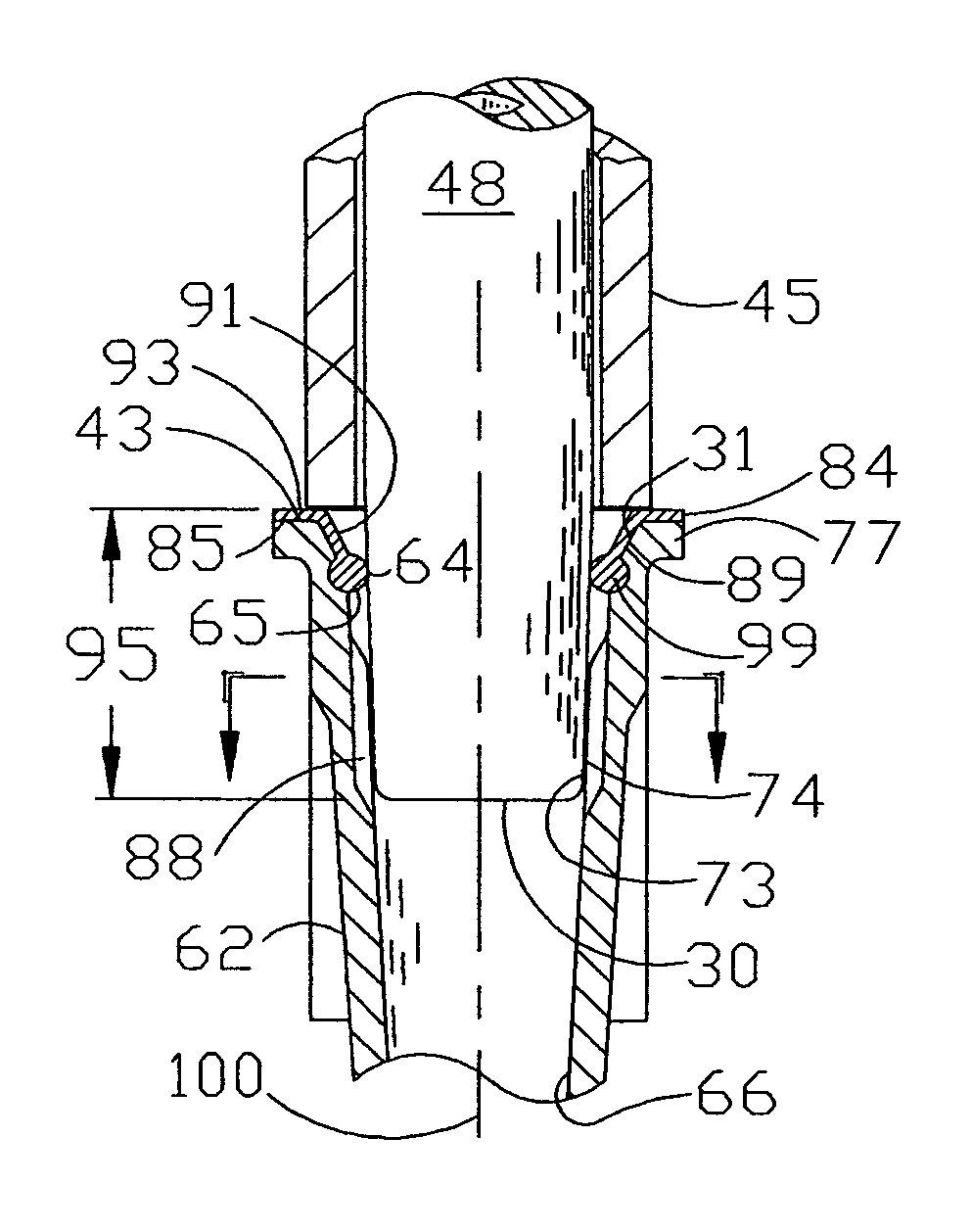
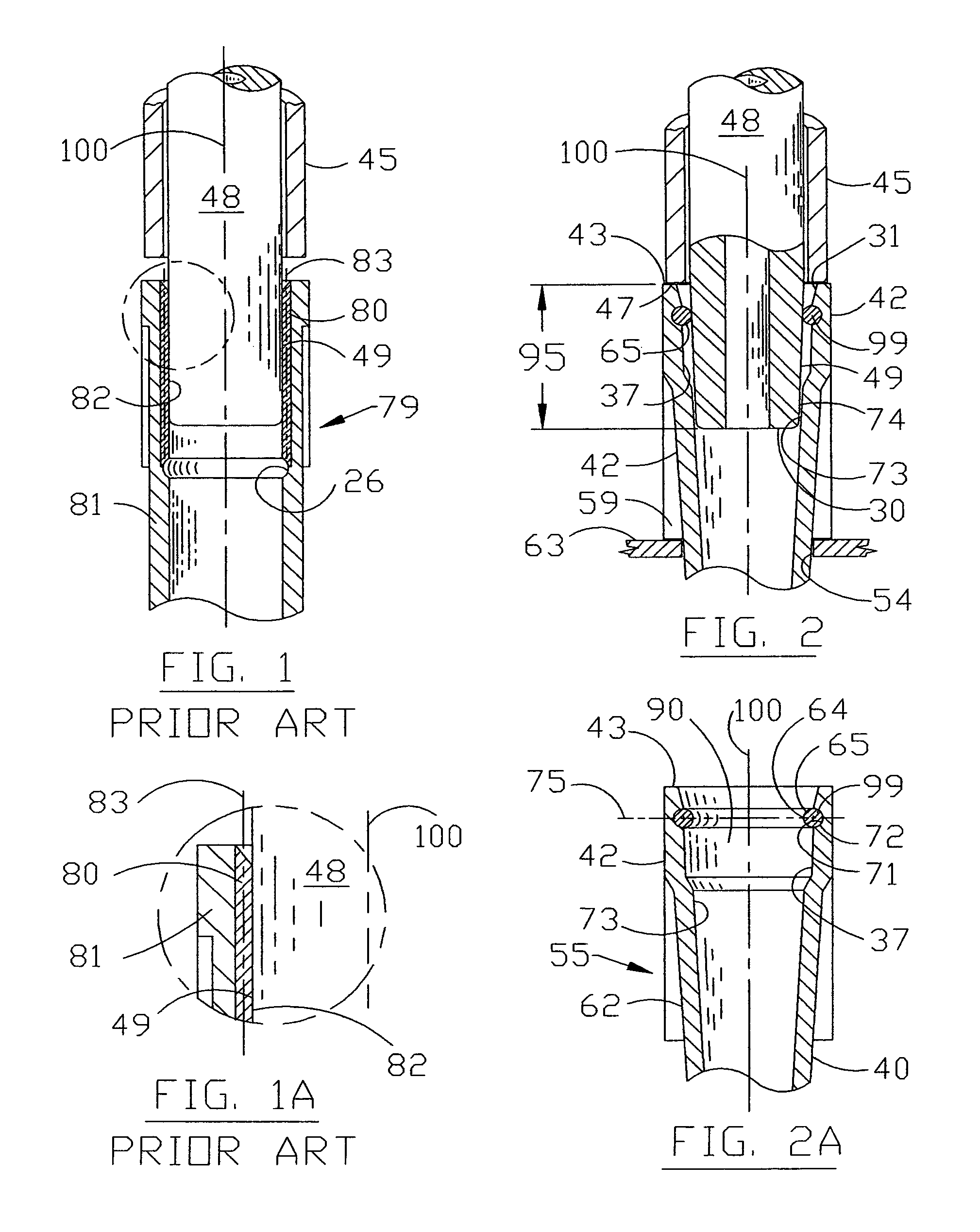
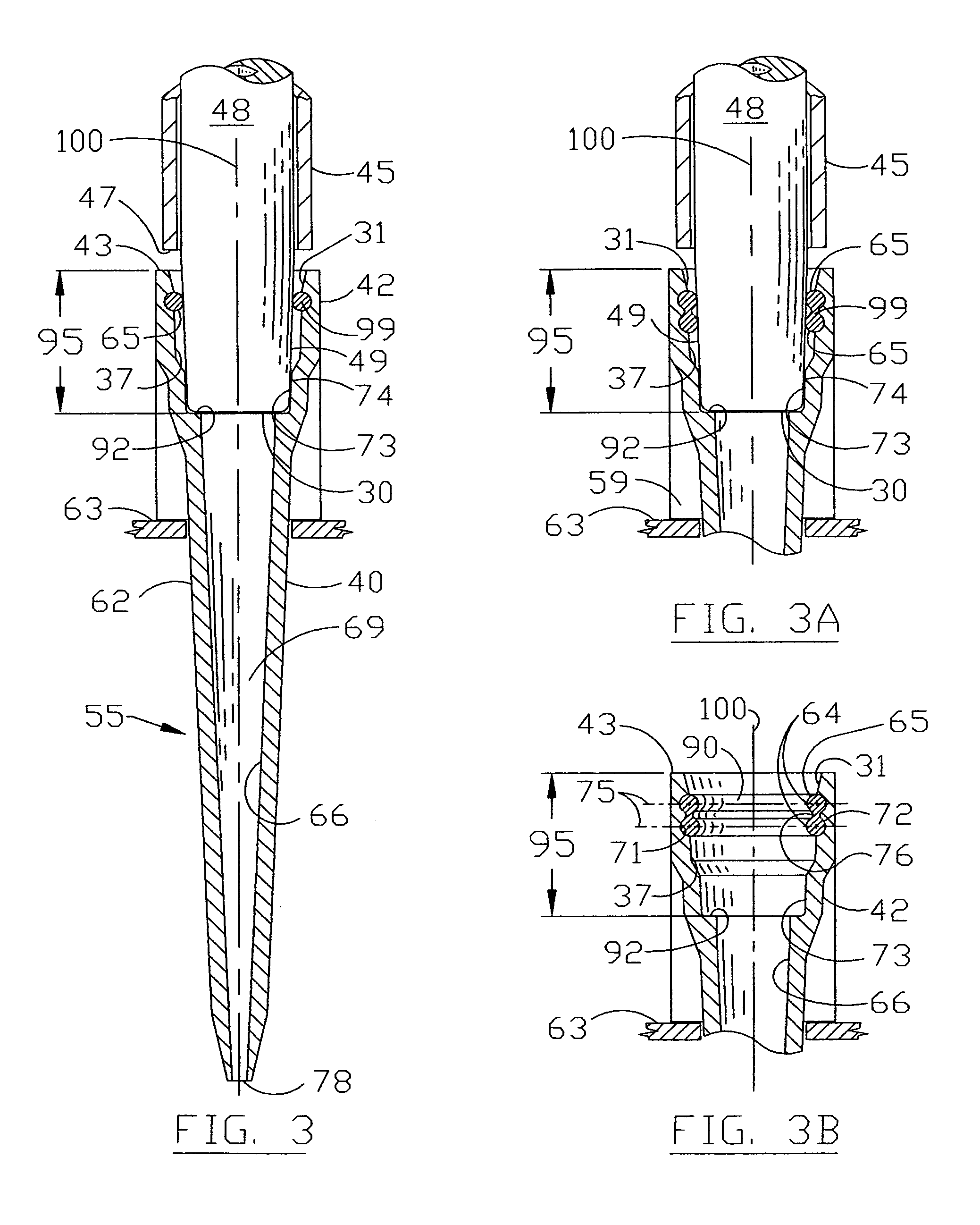
[0068]FIG. 1 and FIG. 1A illustrates a cross section and detail of a prior art U.S. Pat. No. 5,660,797 that includes a two material pipette tip 79 with a pipetter barrel 48 installed for illustration and discussion purposes only. The top end of the tubular member 81 includes an elongated sealing collar 80 that is constructed of a secondary softer material than that of the tubular member 81. The inner collar 80 includes an inner surface 82 that surrounds and engages the mating sealing surface 49 of the pipetter barrel 48 as it enters the uppermost portion of the pipette tip 79. The axis 83 of the elongated inner collar 80 is shown as being longitudinal or parallel in relationship to the longitudinal axis 100 of the pipetter barrel 48 and pipette tip 79. As shown, the large surface contact area between the pipetter barrel sealing surface 49 and that of the soft inner surface 82 of the sealing collar 80 which promotes the sealing of this pipette tip is also longitudinal. These substant...


PUM


Abstract

An ergonomically designed pipette tip that can be securely mounted to a barrel of a pipetter yet is designed to substantially reduce the axial force necessary to install and eject the pipette tip from the pipetter thus reducing the injuries resulting in repetitive stress injury to the thumb and hand. The new ergonomic pipette tip incorporates a separate sealing member constructed from an elastomer that is coupled to the more rigid and chemically inert elongated tubular member that becomes the receptacle for transferring the fluid sample aspirated by the pipetter. The new elastomeric sealing member allows for greater sealing capability or squeeze between the pipetter barrel and the new pipette tip while lowering the coefficient of friction between the mating parts, thus decreasing the axial ejection forces require to overcome the breakaway friction between the new ergonomic pipette tip and the pipetter.

Description

FIELD OF INVENTION[0001]This invention relates to improvements in disposable pipette tips for pipetters or other liquid handling products. More particularly, a pipette tip that is ergonomically designed for air displacement pipetters that can be sealingly and securely mounted to a pipetter barrel that is specifically engineered to reduce the amount of axial force necessary to install and eject the ergonomic pipette tip from the pipetter.BACKGROUND OF INVENTION[0002]Air displacement pipetters with disposable pipette tips have been used in the medical and laboratory industries for many years. The main reason for such continual acceptance comes from the fact that after each use the pipette tip has traditionally been disposed of thereby limiting the possibility of cross contamination between samples. However as tests become more critical and the need to perform many tests from a limited amount of sample quantity became important, laboratory technicians have begun to have problems. These...

Claims


Application Information

Patent Timeline
IPC IPC(8): B01L3/02B01L3/00
CPCB01L3/0275B01L2200/0689B01L2300/021B01L2300/0681B01L2300/123
Inventor SMITH, JAMES C.
Owner SMITH JAMES C
Why Eureka
Try Eureka