Calibratable multidimensional magnetic point sensor

a multi-dimensional, magnetic point sensor technology, applied in the field of hall sensors, can solve the problems of inability to calibrate by a defined magnetic field generated externally, inability to accurately evaluate the magnetic field based on the magnetic field components, and inability to detect magnetic field sensors at different locations, so as to save additional hardware cost or time effor

Active Publication Date: 2012-06-19
FRAUNHOFER GESELLSCHAFT ZUR FOERDERUNG DER ANGEWANDTEN FORSCHUNG EV
View PDF4 Cites 36 Cited by
  • Summary
  • Abstract
  • Description
  • Claims
  • Application Information

AI Technical Summary

Benefits of technology

[0031]Several excitation lines which, relative to the sensor elements arranged in pairs, may comprise different or also mirrored or opposite asymmetries may also be used. Exemplarily, the excitation lines may form coils the magnetic fields of which are superimposed onto one another and thus cause a resulting excitation field in the direction of sensitivity of a sensor element. This has an advantageous effect since the magnetic field sensor may thus be implemented to be calibratable and monitorable during measuring operation.
[0032]Another advantage of the inventive magnetic field sensor and method is that the magnetic field sensor can be calibrated during operation and thus additional hardware cost or time effort can be saved. Exemplarily, the measuring results can be combined and / or evaluated by a micro controller or processor such that additional effort is limited to only one additional calculation operation. The measuring field components and the calibration field components may thus be made available at the same time and in a compensated manner. This is of particular advantage in safety-critical cases of application, such as, for example, in automobile or medical engineering, since the magnetic field sensor can be calibrated and / or adjusted continuously and at the same time its functionality can be monitored, without having to put up with compromises as to quality or quantity of a measurement in many cases.

Problems solved by technology

The arrangement for detecting the spatial magnetic field components, as is exemplarily illustrated in FIG. 7, entails the problem that the magnetic field cannot be measured in one point, but in the respective central points of the individual sensors.
This inevitably entails corruption, since an exact evaluation of the magnetic field based on the magnetic field components, detected at different locations, of the magnetic field sensor, is not possible.
The sensor illustrated entails the problem that it can only be calibrated by a defined magnetic field generated externally and has no excitation line of its own.
Additionally, due to its set-up and its mode of functioning, this sensor cannot be operated using a compensation method, such as, for example, a spinning-current method.
Furthermore, a problem of the arrangement shown in FIG. 8 is that such a semiconductor element, due to contaminations of the semiconductor material, asymmetries in contacting, variations in the crystalic structure, etc., exhibits offset voltages which cannot be suppressed using a corresponding compensation wiring suitable for spinning current.
Monitoring, calibration and testing of the sensors, however, are problematic in these arrangements.

Method used


Image

  • Calibratable multidimensional magnetic point sensor
  • Calibratable multidimensional magnetic point sensor
  • Calibratable multidimensional magnetic point sensor

Examples


Embodiment Construction

[0048]With reference to the following specifications it should be noted, that in the different embodiments same or seemingly same functional elements have the same reference numerals and are thus mutually interchangeable in the different embodiments illustrated in the following.

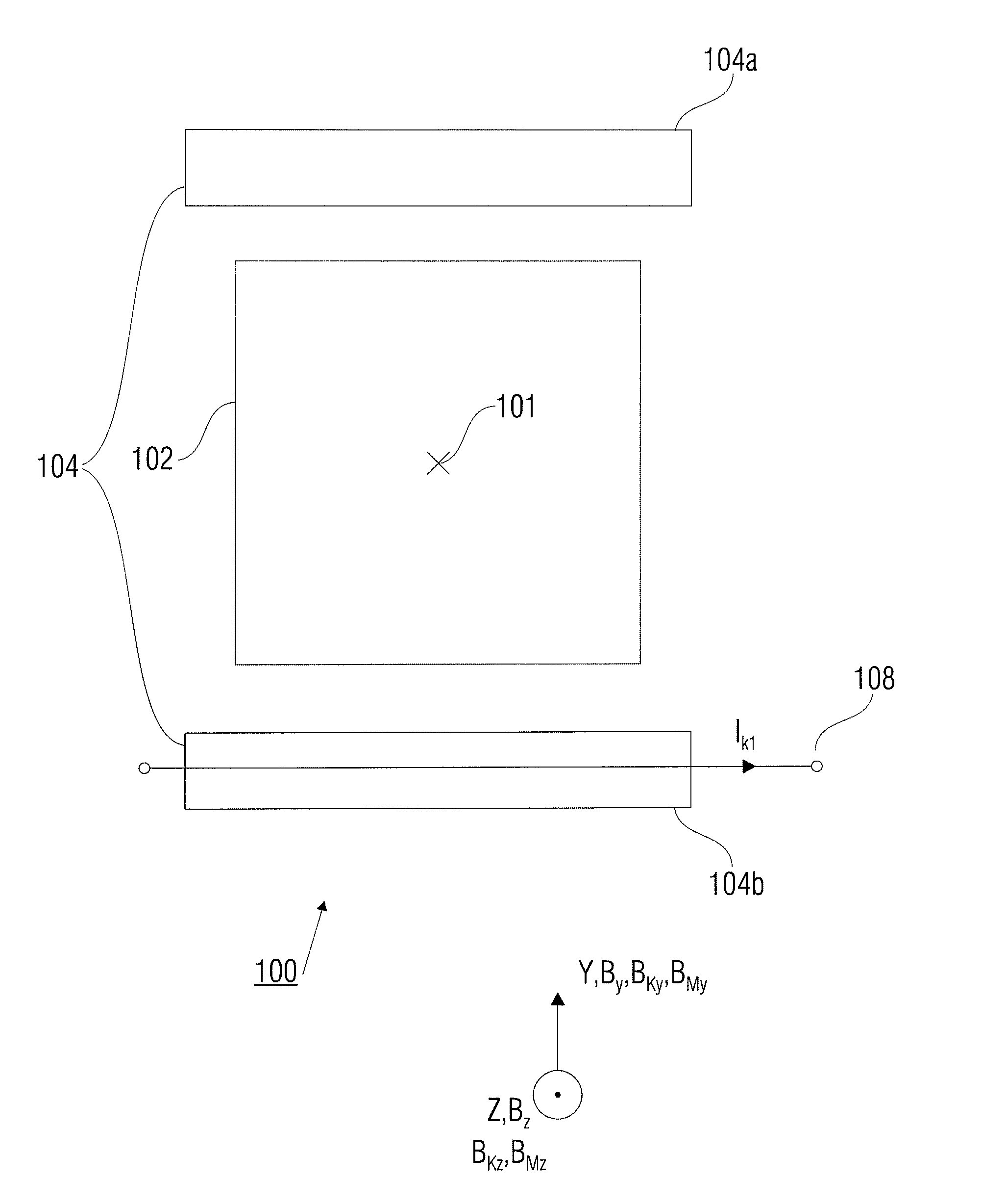
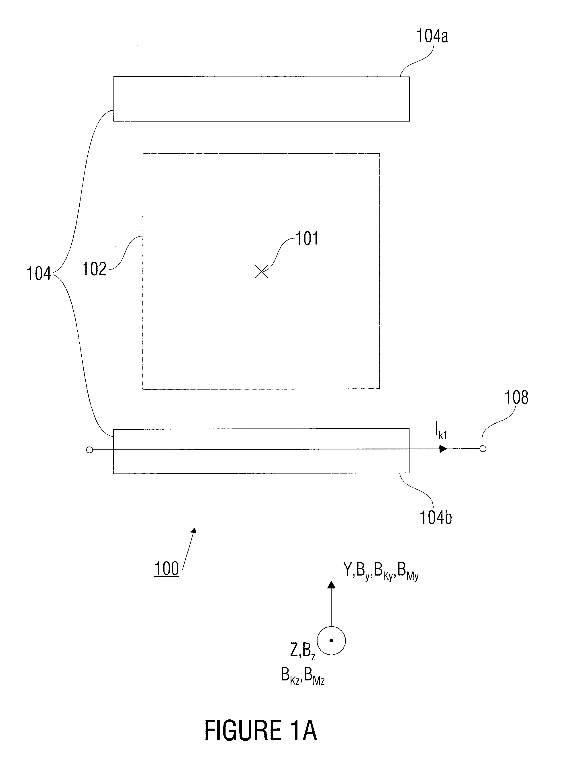
[0049]FIG. 1a shows a calibratable magnet field sensor 100 for detecting a first and a second spatial component (By, Bz) of a magnet field in a reference point 101, wherein the magnetic field comprises and first and a second measurement field component (BMy, BMz) and / or a first and second calibration field component (BKy, BKz). The magnetic field sensor 100 includes a first sensor element arrangement 104 comprising at least a first and a second sensor element (1041a, 104b) for detecting the first magnetic field component By comprising a first measurement field component BMy and / or a first calibration field component BKy, with reference to a first spatial axis y in the reference point 101.

[0050]Further, the ma...


PUM


Abstract

A calibratable magnetic field sensor for sensing a first and a second spatial component of a magnetic field in a reference point, wherein the magnetic field includes a first and a second measurement field component and / or a first and a second calibration field component. The magnetic filed sensor includes a first sensor element arrangement including at least a first and a second sensor element for sensing the first magnetic field component, which includes a first measurement field component and / or a first calibration field component, with respect to a first spatial axis in the reference point. Furthermore, the magnetic field sensor includes a second sensor element arrangement for sensing the second magnetic field component, which includes a second measurement field component and / or a second calibration field component, with respect to a second spatial axis in the reference point. The magnetic filed sensor also includes an excitation line arranged with respect to the first sensor element arrangement so that, when impressing a default current into the excitation line, a pair of different asymmetrical default calibration field components in the first sensor element and in the second sensor element is generated with respect to the first spatial axis in the first sensor element arrangement, wherein the two spatial axes pass along linearly independent position vectors.

Description

CROSS-REFERENCE TO RELATED APPLICATIONS[0001]This application is a National Phase of PCT / EP2008 / 006808 filed 19 Aug. 2007, which claims priority from German Patent Application No. 102007041230.6-35, which was filed on 31 Aug. 2007, and is incorporated herein in its entirety by reference.BACKGROUND OF THE INVENTION[0002]The present invention relates to magnetic field sensors and, in particular, to Hall sensors for detecting spatial components of a magnetic field in a reference point, the sensors being in particular calibratable during measuring operation, and to the calibration and measuring methods employed here.[0003]Apart from measuring magnetic fields as to magnitude and direction, Hall sensor elements which are based on the Hall effect are frequently employed in technology for non-contact contactless signal generators for detecting the position of switches or control elements in a wear-free manner. Another way of application is measuring a current, wherein a Hall sensor element ...

Claims


Application Information

Patent Timeline
Patent Type & Authority Patents(United States)
IPC IPC(8): G01R35/00
CPCG01R33/0017G01R33/075G01R33/07G01R33/0035
Inventor HOHE, HANS-PETERHACKNER, MICHAELSTAHL-OFFERGELD, MARKUS
Owner FRAUNHOFER GESELLSCHAFT ZUR FOERDERUNG DER ANGEWANDTEN FORSCHUNG EV
Why Eureka
Try Eureka