3D polysilicon diode with low contact resistance and method for forming same

a polysilicon diode and low contact resistance technology, applied in the field of data storage technology, can solve the problems of high forward bias current, and inability to withstand high curren

Active Publication Date: 2012-06-26
SANDISK TECH LLC
View PDF12 Cites 83 Cited by
  • Summary
  • Abstract
  • Description
  • Claims
  • Application Information

AI Technical Summary

Problems solved by technology

However, techniques that provide for a higher forward bias current tend to undesirably increase the reverse bias current.
These differences in forward bias currents can present problems when using the diodes to control which memory cells are programmed and read.
Other problems can also arise due to the differences in currents.

Method used


Image

  • 3D polysilicon diode with low contact resistance and method for forming same
  • 3D polysilicon diode with low contact resistance and method for forming same
  • 3D polysilicon diode with low contact resistance and method for forming same

Examples


Embodiment Construction

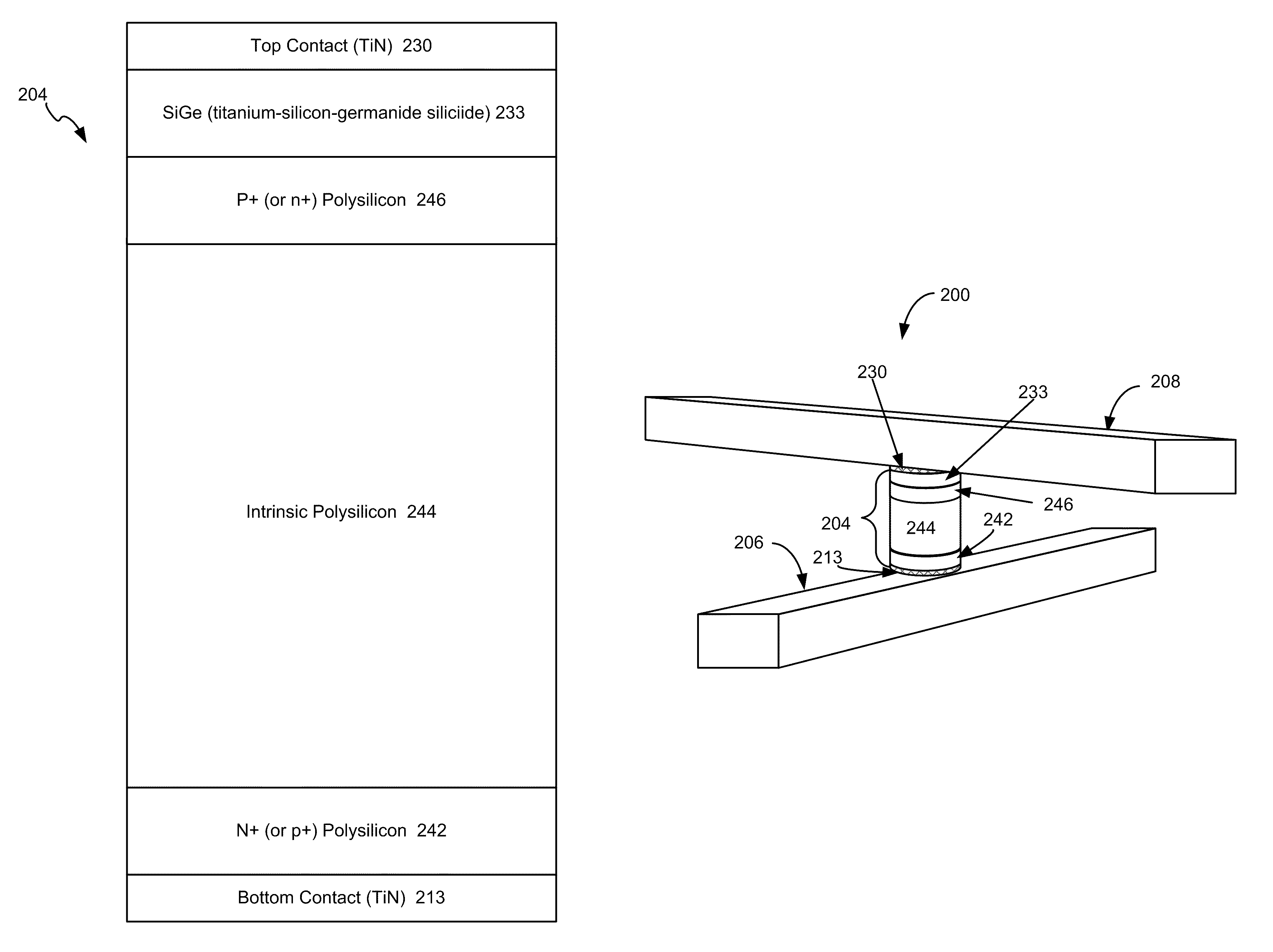
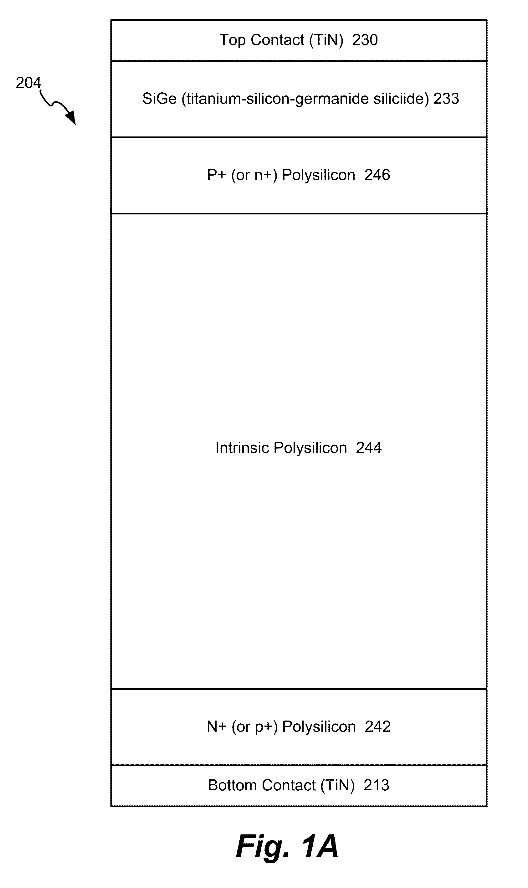
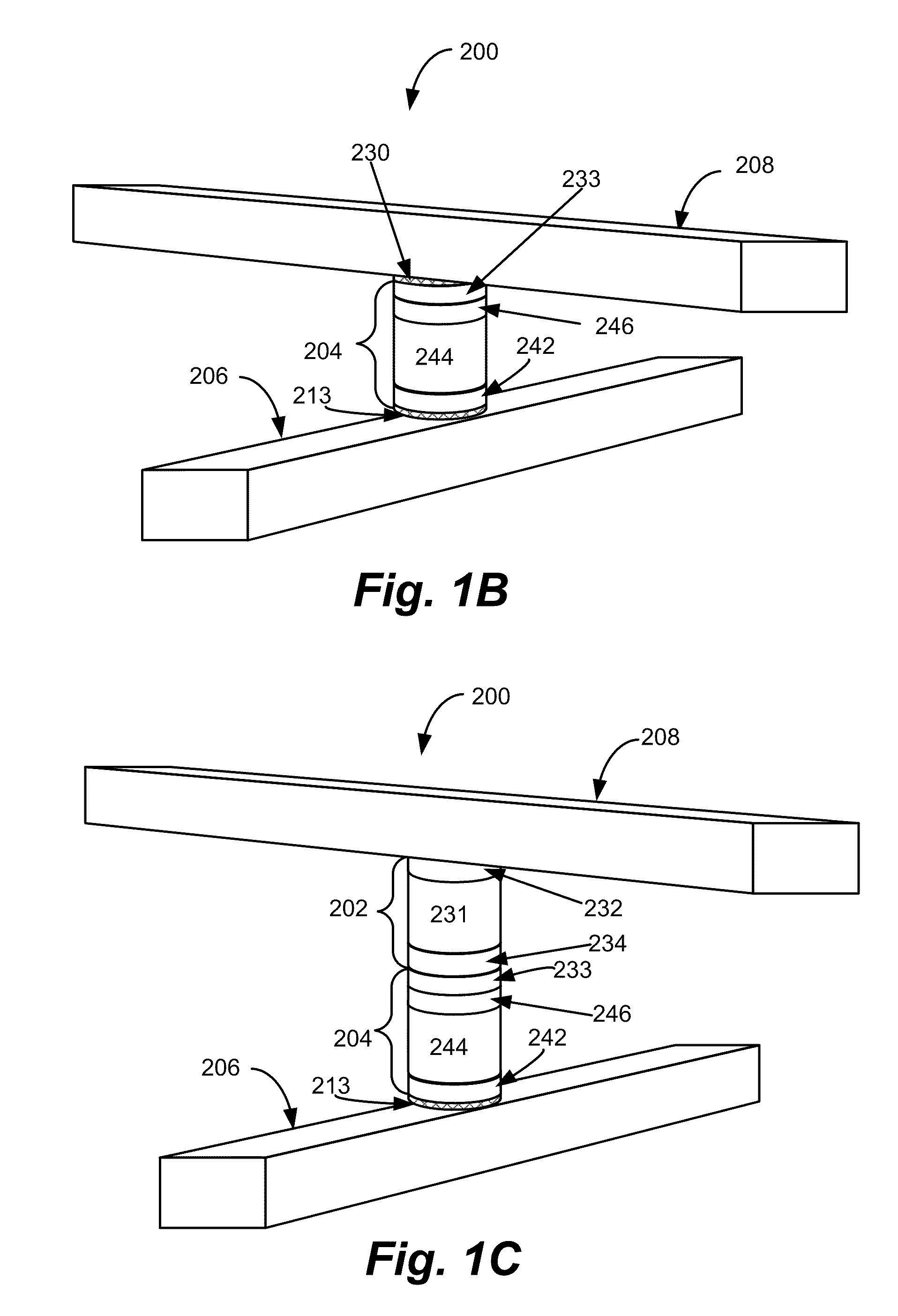
[0021]A semiconductor p-i-n diode and method for forming the same are described herein. Memory arrays having p-i-n diodes and techniques for forming memory arrays having p-i-n diodes are disclosed herein. Techniques disclosed herein provide for a low contact resistance between the p-i-n diode and a top contact, which provides for a good forward bias current. Techniques also provide for a relatively low reverse bias current. Thus, the p-i-n diode has a good rectification ratio. Moreover, techniques disclosed herein provide for forming p-i-n diodes in a memory array such that the forward bias currents substantially match. Specifically, the forward bias currents of up-pointing diodes can be made to substantially match those of down pointing diodes, which may achieve better switching results when used in a 3-D memory array. Having the electrical performance of the up- and down-pointing diodes match can obtain better switching yields of the programmed bits at different levels of the memo...


PUM


Abstract

A semiconductor p-i-n diode and method for forming the same are described herein. In one aspect, a SiGe region is formed between a region doped to have one conductivity (either p+ or n+) and an electrical contact to the p-i-n diode. The SiGe region may serve to lower the contact resistance, which may increase the forward bias current. The doped region extends below the SiGe region such that it is between the SiGe region and an intrinsic region of the diode. The p-i-n diode may be formed from silicon. The doped region below the SiGe region may serve to keep the reverse bias current from increasing as result of the added SiGe region. In one embodiment, the SiGe is formed such that the forward bias current of an up-pointing p-i-n diode in a memory array substantially matches the forward bias current of a down-pointing p-i-n diode which may achieve better switching results when these diodes are used with the R / W material in a 3D memory array.

Description

BACKGROUND[0001]1. Field[0002]The present invention relates to technology for data storage.[0003]2. Description of the Related Art[0004]Semiconductor-based p-i-n diodes are known in the art. These diodes are referred to as p-i-n devices because they include a region that is heavily doped with a p-type conductor (p+ region), an intrinsic region, and a region that is heavily doped with an n-type conductor (n+ region). The intrinsic region is not intentionally doped, but may have a low level of n-type and / or p-type impurities. The p-i-n diode may be formed with materials such as silicon, germanium, silicon germanium, etc. Suitable dopants can be used in the p+ region and the n+ region.[0005]Semiconductor-based p-i-n diodes have a variety of uses. One proposed usage is a memory cell. Published U.S. Patent Application 2005 / 0052915 titled, “Nonvolatile Memory Cell without a Dielectric Antifuse having High- and Low-impedance States,” filed on Sep. 29, 2004 describes a p-i-n diode that has ...

Claims


Application Information

Patent Timeline
Patent Type & Authority Patents(United States)
IPC IPC(8): H01L21/44
CPCH01L29/165H01L29/452H01L29/456H01L29/868H01L27/2409H01L27/2481H01L45/04H01L45/06H01L45/1233H01L45/144H01L45/146H10B63/84H10B63/20H10N70/231H10N70/20H10N70/826H10N70/8828H10N70/8833
Inventor BANDYOPADHYAY, ABHIJITHOU, KUNMAXWELL, STEVEN
Owner SANDISK TECH LLC
Why Eureka
Try Eureka