Modified field generation layer for microwave assisted magnetic recording

a technology of field generation layer and microwave assisted magnetic recording, which is applied in the direction of magnetic recording head, data recording, instruments, etc., can solve the problem that the application of patent applications does not cover all possible schemes

Active Publication Date: 2012-06-26
HEADWAY TECH INC
View PDF13 Cites 51 Cited by
  • Summary
  • Abstract
  • Description
  • Claims
  • Application Information

AI Technical Summary

Problems solved by technology

However, these patent applications do not cover all possible schemes for the top STO case.

Method used


Image

  • Modified field generation layer for microwave assisted magnetic recording
  • Modified field generation layer for microwave assisted magnetic recording
  • Modified field generation layer for microwave assisted magnetic recording

Examples


example 1

On Top [CoFe / Ni]xm Coupled with FeCo as FGL) at Bottom ([CoFe / Ni]xn

[0039]

Ta10 / Ru20 / Cu20 / [CoFe(x %)2 / Ni6]xn / spacer / [CoFe(x %)2 / Ni6]xm / FeCo100 / Ru10 / Ta4 0 / Ru30

[0040]In the above structure, Ta10 / Ru20 / Cu20 is used as a composite seed layer, [CoFe(x %)2 / Ni5]xn multilayer structure as a reference layer, with x % ranging from 0% (pure Co / Ni case) to 90% for CoFe(x %) compositions and n ranging from 5 to 50 with a preferred range from 10 to 30 laminations; the spacer material can be Cu for CPP-GMR or MgO, AlOx, TiOx, ZnO for TMR. FeCo layer of 50 Å to 300 Å is served as the FGL layer. Finally, Ru10 / Ta40 / Ru30 is used as the capping layer.

[0041]The annealing temperature for such devices can be from 150 to 300° C. with a preferred range of 180 to 250° C. and annealing can be from 0.5 hours to 5 hours. In particular, [CoFe(x %)2 / Ni5]xm (with m ranging from 5 to 30 with a preferred range of from 5 to 20) is inserted underneath the FeCo100 layer; since the [CoFe / Ni]xm layer is strongly magneticall...

example 2

On Top [CoFe / Ni]xn at Bottom [CoFe / Ni]xm Coupled with FeCo as FGL

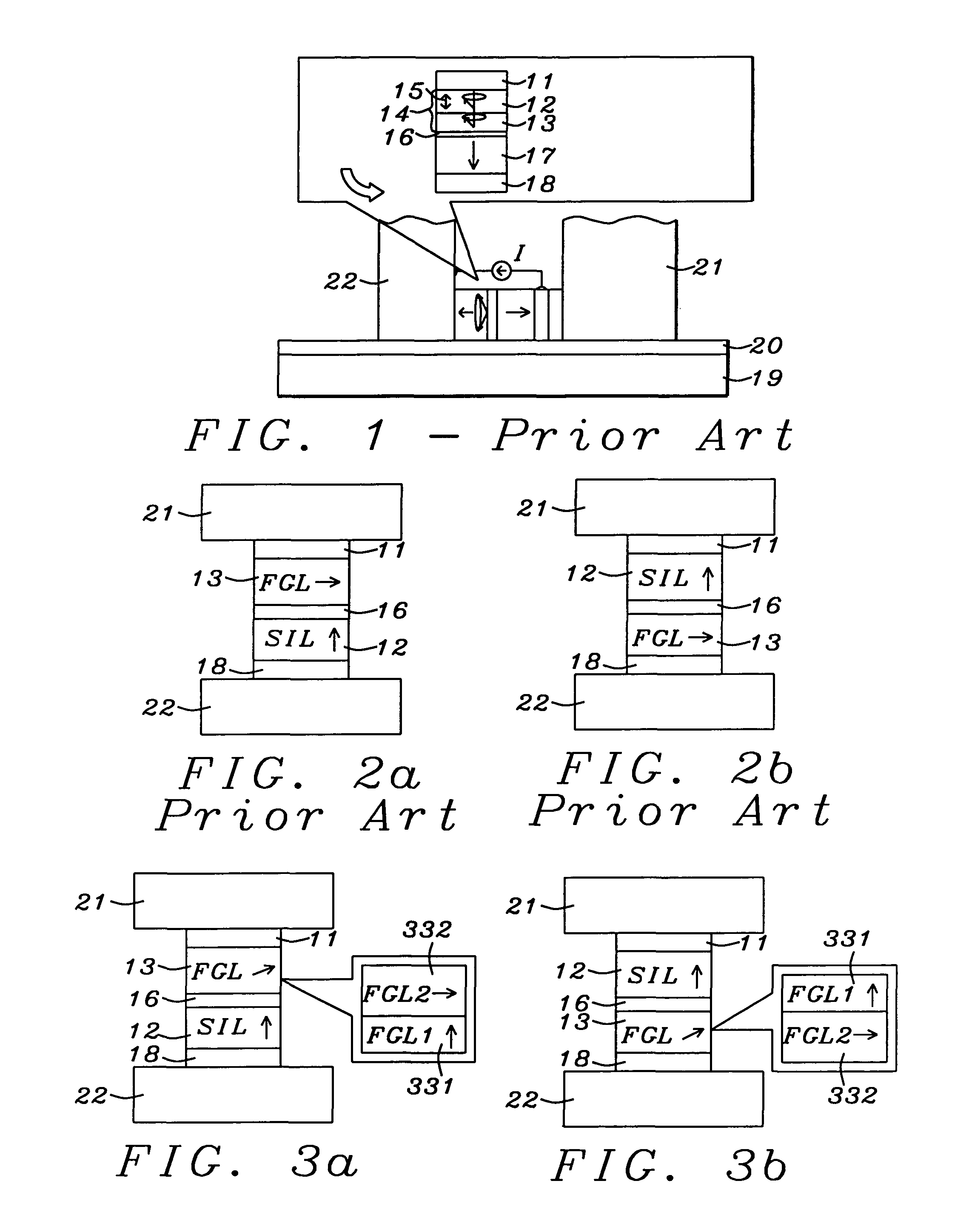
[0047]As a preferred embodiment, a top type (SIL layer on the top) structure with the following configuration was fabricated. Each value next to the individual layer indicates the film thickness in angstroms.

[0048]Ta10 / Ru20 / Cu20 / FeCo100 / [CoFe(x %)2 / Ni5]xm / spacer / [CoFe(x %)2 / Ni5]xn / Ru10 / Ta4 0 / Ru30

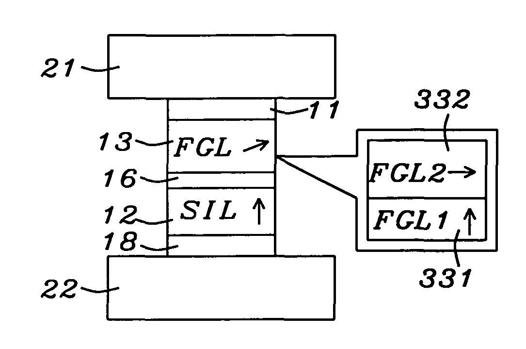
[0049]In the above structure, [CoFe(x %)2 / Ni5]xm (with m ranging from 5 to 30 with a preferred range of 5 to 20) is inserted on top of the FeCo100 layer, since the [CoFe / Ni]xm layer is magnetic coupled with FeCo layer strongly, the strong PMA of the [CoFe(x %)2 / Ni5]xm will force the anisotropy of the FeCo to tilt partially toward perpendicular direction whereby the full FGL was able to oscillate at current densities as low as 1×10⁸ A / cm2.

[0050]Similar data for the bottom STO case was also achieved.

[0051]In summary, when the FGL layer next to the spacer has high PMA, better device performance results due to easier FGL oscillatio...


PUM

PropertyMeasurementUnit
frequenciesaaaaaaaaaa
frequencyaaaaaaaaaa
temperatureaaaaaaaaaa

Abstract

A spin torque oscillator is described in which the conventional Field Generation Layer (FGL) is replaced by a bilayer, one of whose members exhibits perpendicular magnetic anisotropy while the other exhibits conventional in-plane anisotropy. Provided the layer with the perpendicular anisotropy is the one that is closest to the spacer layer, the device is able to generate microwaves at current densities as low as 1×10⁸ A / cm2.

Description

FIELD OF THE INVENTION[0001]The invention relates to the general field of microwave assisted magnetic recording with particular reference to the design of the field generator portion of the spin torque oscillator.BACKGROUND OF THE INVENTION[0002]Microwave assisted magnetic recording, MAMR, is one of several future technologies that are expected to extend perpendicular magnetic recording beyond 1 terabit per square inch. In this scheme, a field generator is placed in close proximity to the write element to produce a high frequency oscillating field in the media film plane. The frequency range of the oscillating field could be from 5 GHz to 50 GHz. Because of ferromagnetic resonance (FMR), it becomes possible to switch media grains at fields below their normal coercivity i.e. a lower write field may be used, but only in the immediate vicinity of the microwave assisted write element.[0003]A microwave field generator is basically a spin torque oscillator (STO). It resembles a current-pe...

Claims


Application Information

Patent Timeline
Patent Type & Authority Patents(United States)
IPC IPC(8): G11B5/127
CPCG11B5/1278G11B5/3133G11B2005/001G11B2005/0024
Inventor ZHANG, KUNLIANGLI, MINZHOU, YUCHEN
Owner HEADWAY TECH INC
Why Eureka
Try Eureka