
Projector apparatus which controls pulse widths of light beams emitted from pulse-driven light sources of different colors based on deterioration levels thereof

a projector and light beam technology, applied in the direction of non-linear optics, optical radiation measurement, instruments, etc., can solve the problems of inability to project images with a higher luminance, led deterioration, and inability to adjust the chromaticity of the projected image, so as to achieve the effect of adjusting the chromaticity of the image and the luminan

Active Publication Date: 2012-07-03
CASIO COMPUTER CO LTD
View PDF11 Cites 1 Cited by
  • Summary
  • Abstract
  • Description
  • Claims
  • Application Information

AI Technical Summary

Benefits of technology

[0011]It is an object of the present invention to provide a projector apparatus, a control program for the projector apparatus and a light source controlling method for the projector apparatus which can project an image with a higher luminance and adjust chromaticity of the image.

Problems solved by technology

However, the projector apparatus which uses the three LEDs cannot project an image with a higher luminance.
Moreover, an LED deteriorates as the LED is used longer (as emitting time becomes longer).
Therefore, according to Jpn. Pat. Appln. KOKAI Publication No. 2004-317558, although an image can be projected with a higher luminance, chromaticity adjustment for the projected image is impossible.

Method used


Image

  • Projector apparatus which controls pulse widths of light beams emitted from pulse-driven light sources of different colors based on deterioration levels thereof
  • Projector apparatus which controls pulse widths of light beams emitted from pulse-driven light sources of different colors based on deterioration levels thereof
  • Projector apparatus which controls pulse widths of light beams emitted from pulse-driven light sources of different colors based on deterioration levels thereof

Examples


Embodiment Construction

[0035]Hereinafter, an embodiment of the present invention will be described with reference to the accompanying drawings. Some limitations may be set on the embodiment for a technical reason; however, a scope of the invention will not be limited to the embodiment and the drawings described hereinafter.

[0036]An explanation will be given on one embodiment of the invention referring to the drawings.

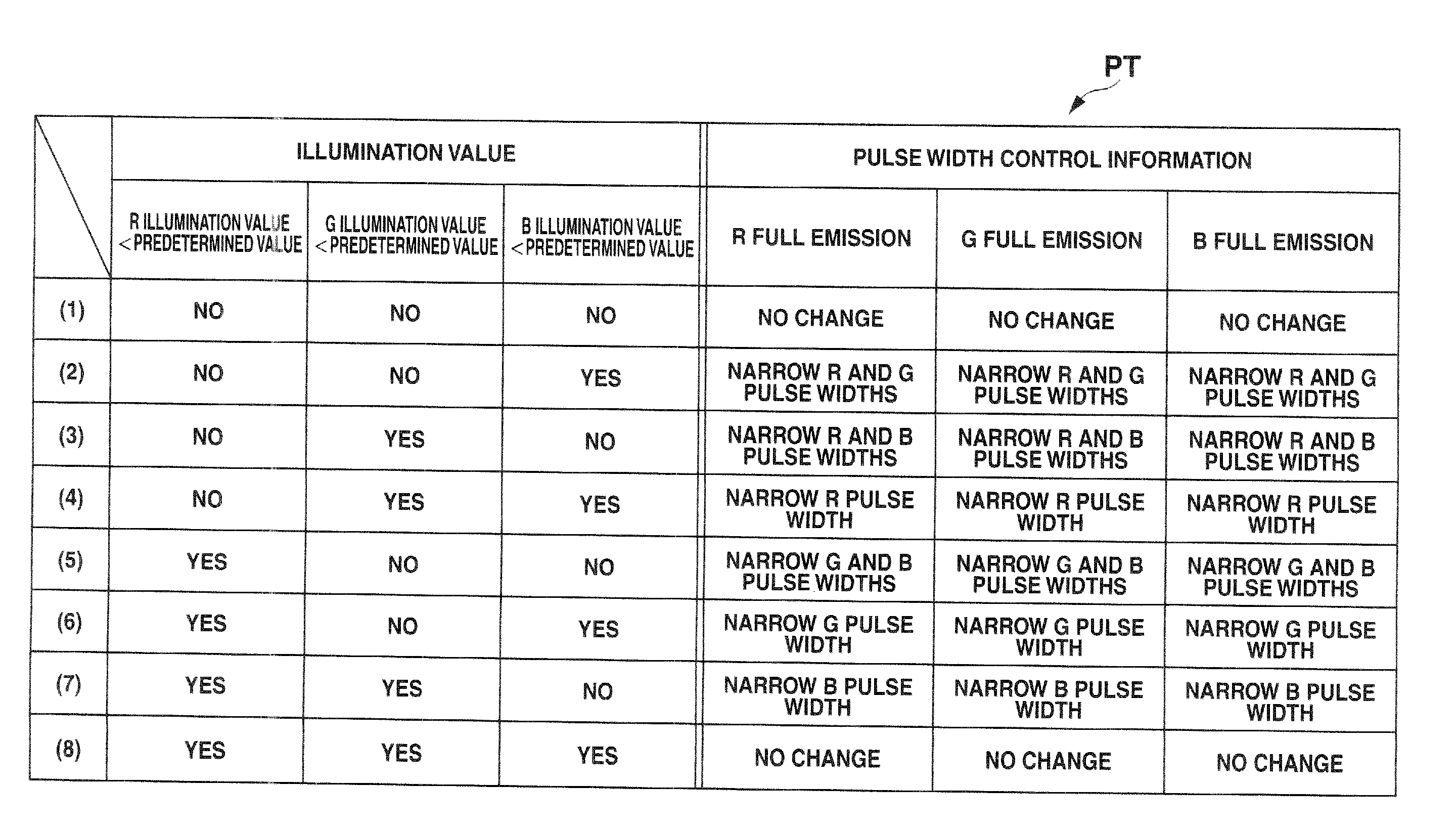
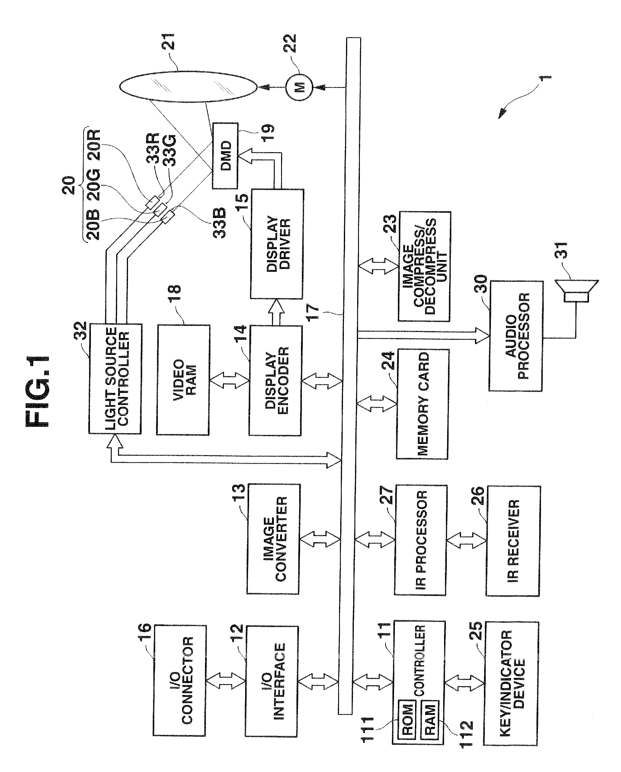
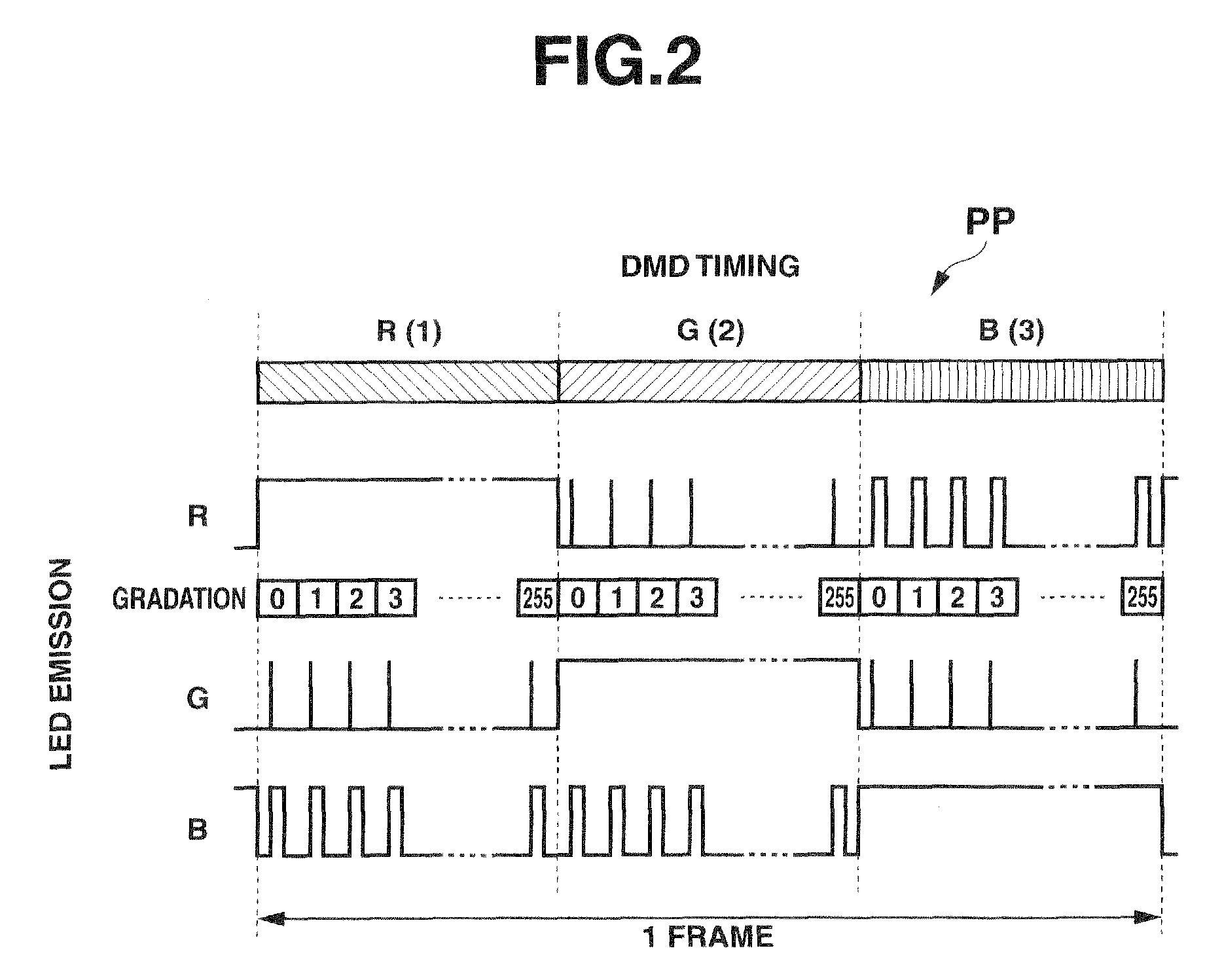
[0037]FIG. 1 is a block diagram showing an electronic configuration of a projector apparatus 1 according to an embodiment. The projector apparatus 1 includes a controller 11, an input-output (I / O) interface 12, an image converter 13, a display encoder 14, and a display driver 15. In addition, the projector apparatus 1 includes input-output (I / O) connector unit 16 and a system bus 17. An image signal (or image data) complying with one of the various standards is input to the I / O connector unit 16, and the image signal is sent to the image converter 13 via the I / O interface 12 and the system bu...


PUM


Abstract

A projector apparatus includes a light source configured to emit light beams of a plurality of color components, emissions of the light beams being controlled individually, a projection unit configured to form images respectively corresponding to the color components using the light beams from the light source for each frame and to sequentially project the images, a driving unit configured to drive the light source so that the light beams are emitted as light pulses having respectively predetermined pulse widths for a period in which the projection unit projects each of the images, a detector configured to detect deterioration levels of the light source respectively for the color components, and a controller configured to control the pulse widths of the light beams emitted from the light source based on the deterioration levels.

Description

CROSS-REFERENCE TO RELATED APPLICATIONS[0001]This application is based upon and claims the benefit of priority from prior Japanese Patent Application No. 2008-245247, filed Sep. 25, 2008, the entire contents of which are incorporated herein by reference.BACKGROUND OF TEE INVENTION[0002]1. Field of the Invention[0003]The present invention relates to a projector apparatus, a control program for the projector apparatus and a light source controlling method for the projector apparatus. The projector apparatus uses light sources which emit light beams of different colors to project an image.[0004]2. Description of the Related Art[0005]Conventionally, a projector apparatus having a halogen lamp light source has been used in general. In recent years, a projector apparatus which employs, as light sources, three LEDs respectively emitting red, green and blue light beams has been proposed to downsize the apparatus and to make the apparatus portable. However, the projector apparatus which uses...

Claims


Application Information

Patent Timeline
Patent Type & Authority Patents(United States)
IPC IPC(8): G03B21/20G01J1/32
CPCG03B21/14H04N9/3111H04N9/3155H04N9/3158H04N9/3194H04N9/3197H05B33/086H05B33/0869G03B33/08H05B45/22G02F1/133G03B21/00H05B45/20
Inventor SHIBASAKI, MAMORU
Owner CASIO COMPUTER CO LTD
Learn More