Linear detector with added diode feedback loop

a feedback loop and detector technology, applied in the field of linear detectors, can solve the problems of poor sensitivity level of linear diode detector detection at a low power range, prior art linear diode detectors will not meet the present dynamic range requirements, and the present requirements of 2g detectors require a nearly 40 db dynamic range, so as to improve the sensitivity and dynamic range of linear diode detectors.

Active Publication Date: 2012-07-10
QORVO US INC
View PDF4 Cites 4 Cited by
  • Summary
  • Abstract
  • Description
  • Claims
  • Application Information

AI Technical Summary

Benefits of technology

[0006]A feedback diode provides a feedback of the voltage signal at the detector output to the anode of the rectifier diode to improve the sensitivity and dynamic range of the linear diode detector. In order to provi...

Problems solved by technology

However, a linear diode detector has a poor sensitivity level of detection at a low power range.
Prior art linear diode detectors will not meet the present dynamic range requirements after taking into consideration control loop gain and p...

Method used


Image

  • Linear detector with added diode feedback loop
  • Linear detector with added diode feedback loop
  • Linear detector with added diode feedback loop

Examples


Embodiment Construction

[0015]The embodiments set forth below represent the necessary information to enable those skilled in the art to practice the disclosure and illustrate the best mode of practicing the disclosure. Upon reading the following description in light of the accompanying drawing figures, those skilled in the art will understand the concepts of the disclosure and will recognize applications of these concepts not particularly addressed herein. It should be understood that these concepts and applications fall within the scope of the disclosure and the accompanying claims.

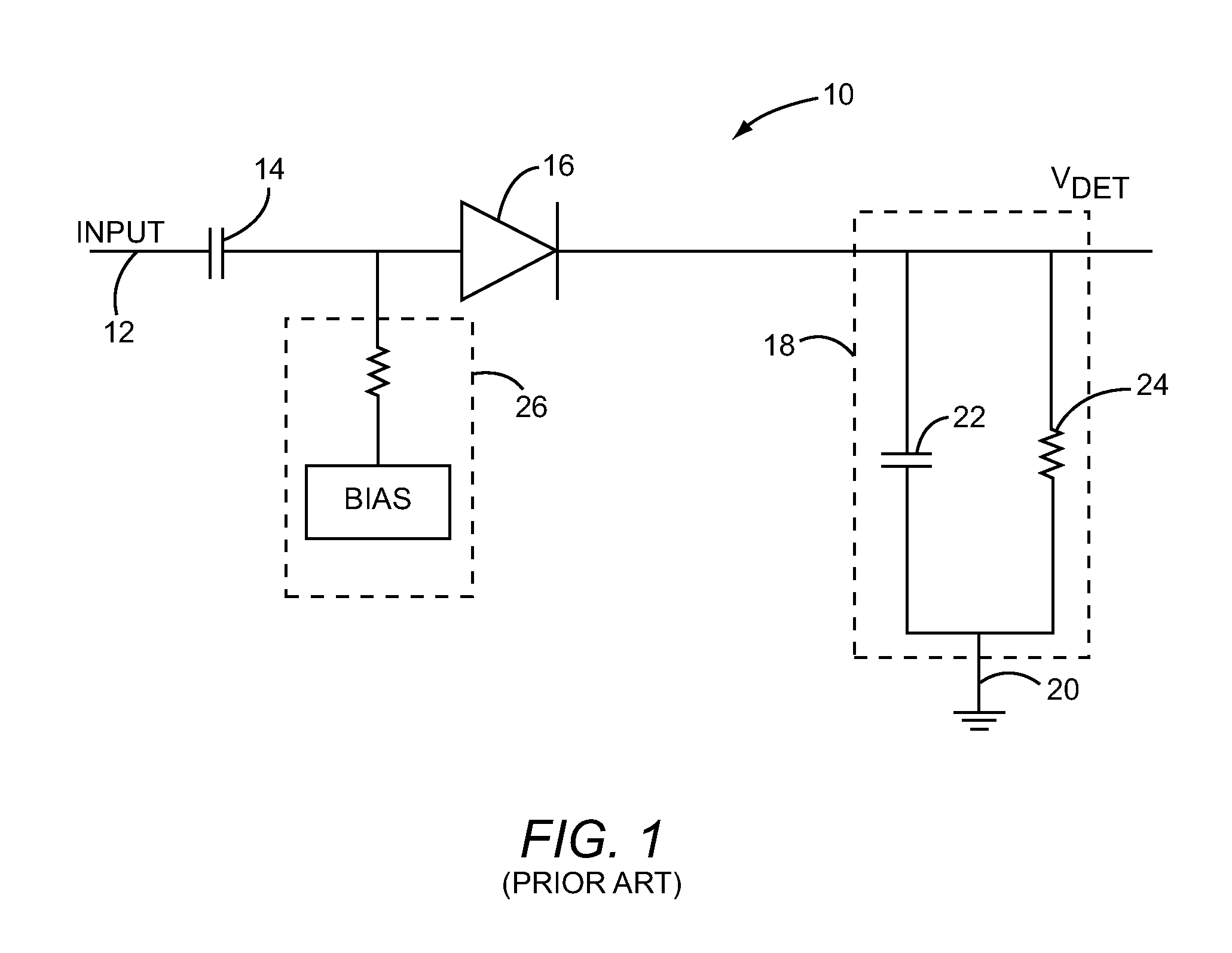
[0016]FIG. 1 is a circuit diagram for a linear diode detector 10 according to the prior art. The linear diode detector 10 has a signal input 12. A direct current (DC) blocking capacitor 14 has a first terminal coupled to the signal input 12 and a second terminal coupled to an anode of a rectifier diode 16. A cathode of the rectifier diode 16 provides an output for a detector voltage (VDET). A low pass filter 18 is coupled betwe...


PUM


Abstract

A linear diode detector having an increased dynamic range and an improved sensitivity level is described. The linear diode detector includes a signal input that receives a sample of output power from a power amplifier (PA). A detector output provides a voltage signal that is usable by power control circuitry to maintain a constant output power for the PA. A rectifier diode has an anode communicatively coupled to the signal input, and a cathode that is communicatively coupled to the detector output. A low pass filter is communicatively coupled to the detector output to filter out high frequency components of a rectified sample of output power. The anode of a feedback diode is communicatively coupled to the detector output, and the cathode of the feedback diode is communicatively coupled to the anode of the rectifier diode in order to feedback a portion of the voltage signal to increase detection sensitivity.

Description

FIELD OF THE DISCLOSURE[0001]The present disclosure relates to a linear detector that is typically used to sample a radio frequency (RF) transmitter output, and in particular to a linear detector having improved detector sensitivity for providing feedback to RF transmitter circuitry.BACKGROUND OF THE DISCLOSURE[0002]Gain control circuitry for a power amplifier (PA) of a mobile terminal relies on feedback from a sample of output power taken from the output of the PA. Traditionally, a relatively inexpensive linear diode detector is preferred for providing a sample of output power. Usually, a linear diode detector receives a sample of output power from a directional coupler that is in communication with the output of the PA. In order not to negatively affect a desired output power level of the PA, the directional coupler is set to a relatively low coupling factor that will just meet the sensitivity requirements of the linear diode detector. However, a linear diode detector has a poor s...

Claims


Application Information

Patent Timeline
IPC IPC(8): H03G3/20
CPCG01R21/10
Inventor BUI, HIEN D.RICHARD, STEPHEN E.
Owner QORVO US INC
Why Eureka
Try Eureka