Position measuring system, position measuring method and position measuring program

a technology of position measurement and program, which is applied in the direction of distance measurement, instruments, surveying and navigation, etc., can solve the problems of difficult installation of targets, unavoidable area, and complicated installation procedures of targets, so as to reduce the amount of processing data, improve processing speed, and save storage capacity

Active Publication Date: 2012-07-10
KK TOPCON
View PDF13 Cites 44 Cited by
  • Summary
  • Abstract
  • Description
  • Claims
  • Application Information

AI Technical Summary

Benefits of technology

[0005]It is an object of the invention to provide a position measuring system, which can eliminate the defects in the prior art as described above.
[0006]To attain the above object, the present invention provides a position measuring system, which comprises a distance measuring unit for projecting and scanning a pulsed beam for measurement to a measurement area and for measuring a distance based on a reflected light of the pulsed beam for measurement and for obtaining a position data group in the measurement area, a digital image pickup unit for acquiring an image data by taking an image of the measurement area, a storage unit for storing at least two sets of the position data groups and the image data acquired from at least two directions by interrelating and associating the position data groups with the image data, and an arithmetic unit for synthesizing the at least two position data groups through matching of the two images based on the two stored image data. Also, the present invention provides the position measuring system as described above, which further comprises a sight, wherein the arithmetic unit sets up the measurement area by using the sight, wherein in the case where the measurement area extends beyond a range of a single image pickup, the arithmetic unit calculates a dividing aspect, picks up divided images two or more times, synthesizes the divided images, and obtains an image of the measurement area. Further, the present invention provides the position measuring system as described above, wherein the arithmetic unit prepares polygonal meshes from the position data group, and the polygonal meshes are interrelated and matched with the image data. Also, the present invention provides the position measuring system as described above, wherein the arithmetic unit approximately sets up at least three points or more common to the two image data, and, after performing coordinate transformation on one of the images with reference to the three points or more, matching is performed on the two images, and coordinate transformation is further conducted by using the coordinates obtained by the image matching. Further, the present invention provides the position measuring system as described above, wherein the arithmetic unit approximately sets up three points or more common to the two image data, sets up a template for an area as required including common points in one of the images, sets up a search area which is larger than the template in the other of the images so that the common points are included, and performs image matching by least squares matching method on the images of the template and the image of the search area. Also, the present invention provides the position measuring system as described above, wherein the arithmetic unit sets up at least three points or more common to the position data groups when two or more position data groups are to be synthesized, performs coordinate transformation by using all of the position data groups with reference to the points, and adjusts the synthesis of total position data groups.

Problems solved by technology

On the other hand, in this type of measuring system, the object to be measured is a three-dimensional object, and it is unavoidable that there is an area, which cannot be measured by the measurement from a single point.
According to the prior art, however, a target must be installed on the object to be measured, and this means that complicated procedure is required for the installation of the target.
Also, it is difficult to install the target when the object to be measured is located at high position.
There has been such problems that the characteristics such as irregular surfaces or the like may exert detrimental influence on the accuracy of the synthesis.

Method used


Image

  • Position measuring system, position measuring method and position measuring program
  • Position measuring system, position measuring method and position measuring program
  • Position measuring system, position measuring method and position measuring program

Examples


first embodiment

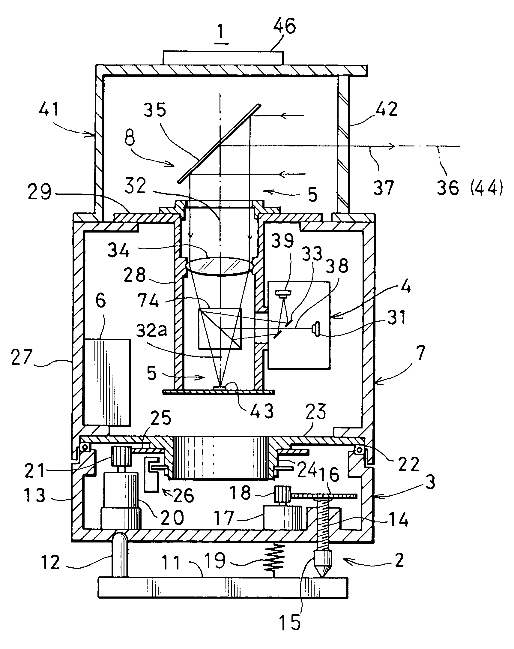
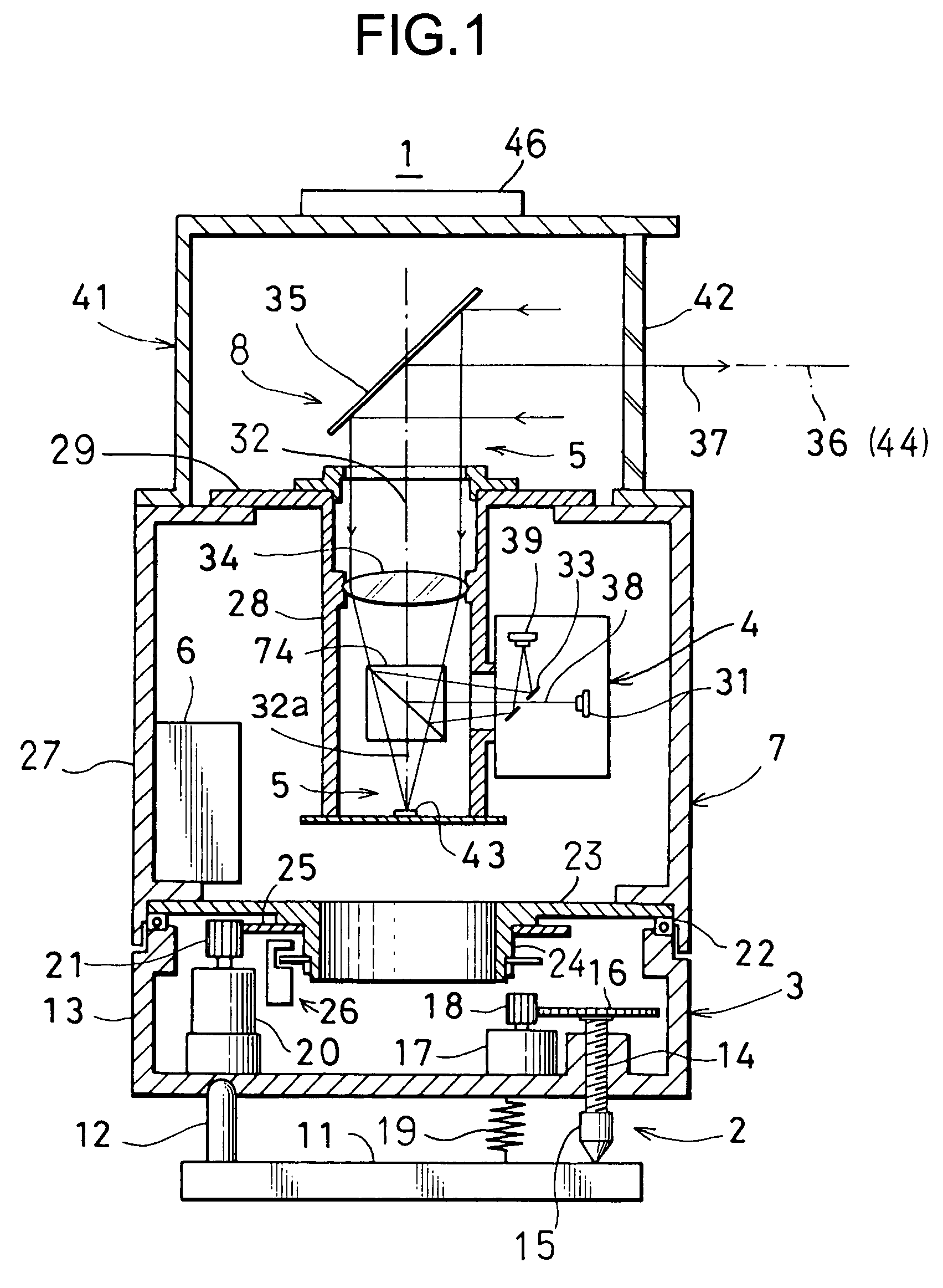
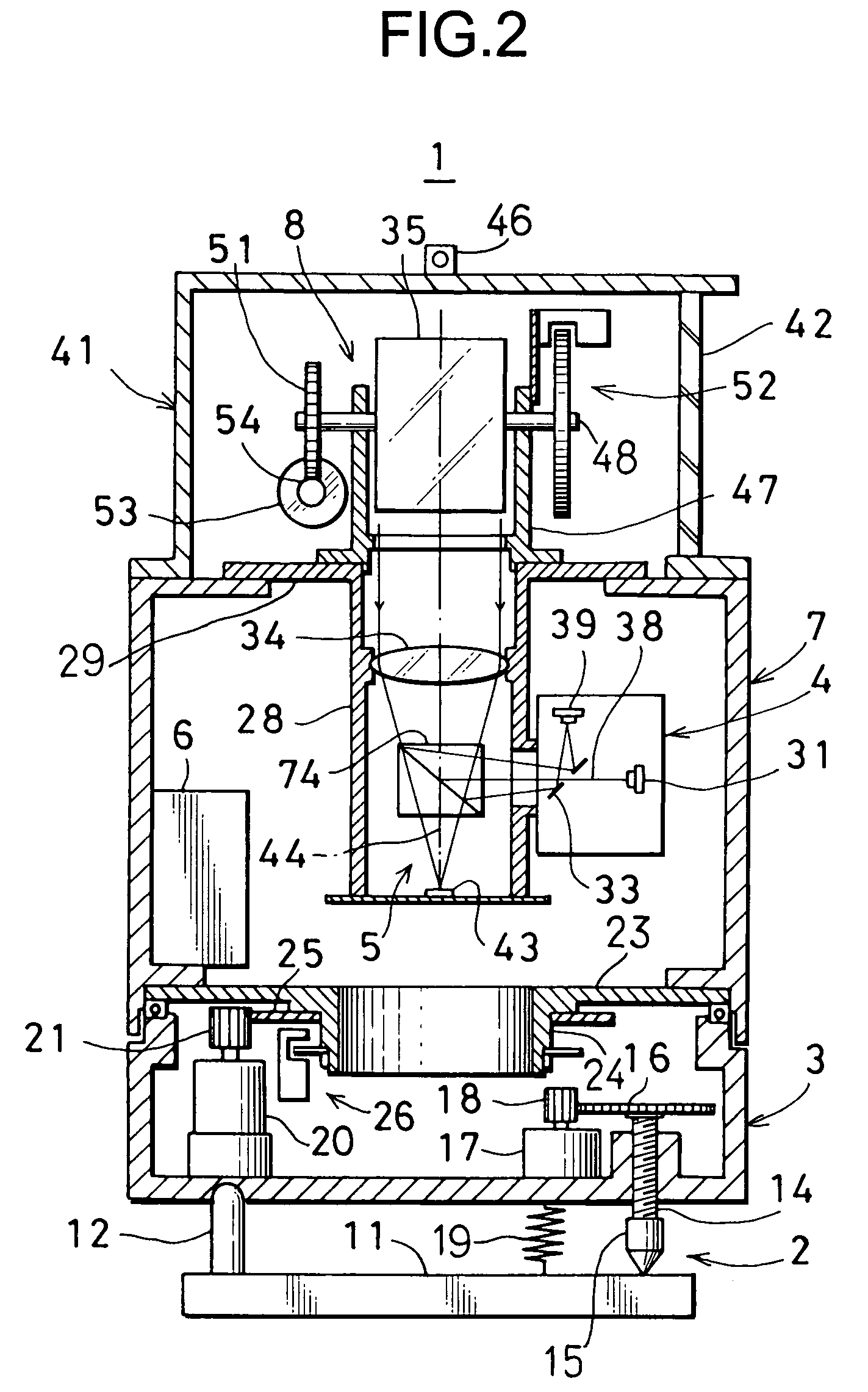
[0038]FIG. 1 and FIG. 2 each represents a position measuring system in the invention.

[0039]A position measuring system 1 primarily comprises a leveling unit 2, a rotary mechanism 3 installed on the leveling unit 2, a measuring system main unit 7 supported by the rotary mechanism 3 and including a distance measuring unit 4, an image pickup unit 5, a control unit 6, etc., and a rotary projecting unit 8 mounted on an upper portion of the measuring system main unit 7. For convenience purpose, FIG. 2 shows the condition of the system when only the rotary projecting unit 8 is seen from a lateral direction with respect to FIG. 1.

[0040]Now, description will be given on the leveling unit 2.

[0041]A pin 12 is erected on a base unit 11. An upper end of the pin 12 is designed with a curved surface and is tiltably engaged in a depression portion on a bottom surface of a lower casing 13. At two other points on the bottom surface, adjusting screws 14 are screwed in and are penetrating through. On a...

second embodiment

[0137]FIG. 17 and FIG. 18 each represents the position measuring system 1 in the invention. The relation between FIG. 17 and FIG. 18 is similar to the relation between FIG. 1 and FIG. 2. In FIG. 17 and FIG. 18, the same component as in FIG. 1 and FIG. 2 are referred by the same symbol and detailed description is not given here.

[0138]In the second embodiment, the rotary mechanism 3 used in the first embodiment is simplified. The arrangement that the emission light optical axis 32 and the image pickup optical axis 44 are optically separated from each other, is the same as in the first embodiment. In the second embodiment, also, infrared light is used as the distance measuring light.

[0139]An upper end shaft unit 75 to form a part of the body tube 28 is disposed on an upper end of the body tube 28 where an image receiving unit 43, a beam splitter 74, a condenser lens 34, etc. are accommodated, and a rotary base 77 is rotatably mounted on the upper end shaft unit 75 via bearings 76. A mi...


PUM


Abstract

A position measuring system, comprising a distance measuring unit for projecting and scanning a pulsed beam for measurement to a measurement area and for measuring a distance based on a reflected light of the pulsed beam for measurement and for obtaining a position data group in the measurement area, a digital image pickup unit for acquiring an image data by taking an image of the measurement area, a storage unit for storing at least two sets of the position data groups and the image data acquired from at least two directions by interrelating and associating the position data groups with the image data, and an arithmetic unit for synthesizing the at least two position data groups through matching of the two images based on the two stored image data.

Description

BACKGROUND OF THE INVENTION[0001]The present invention relates to a position measuring system, a position measuring method, and a position measuring program for preparing positional data with an image of a predetermined measurement area.[0002]A three-dimensional measuring system, i.e. a so-called laser scanner, has been known in the past. According to this three-dimensional measuring system, a pulsed beam for measurement is projected to an object to be measured for scanning, and a distance is measured according to a light reflected from the object to be measured. Three-dimensional measurement of the object to be measured is conducted according to a value of the measured distance and a value of a projection angle of the light, and position data is obtained. In this type of three-dimensional measuring system, three-dimensional point group data is obtained by calculating based on the measured distance value and the projection angle of the light. A type of measuring system is known, by ...

Claims


Application Information

Patent Timeline
Patent Type & Authority Patents(United States)
IPC IPC(8): G01C3/08
CPCG01C15/002
Inventor OTANI, HITOSHIITO, TADAYUKI
Owner KK TOPCON
Why Eureka
Try Eureka