Wireless relay communication system and method

a relay communication and relay technology, applied in the field of wireless communication, can solve the problems of affecting the communication performance reducing the throughput of the subscriber station, and limiting the coverage of the entire network, so as to achieve the effect of extending the coverage of the bs and the throughput of the subscriber terminal

Active Publication Date: 2012-07-10
HUAWEI TECH CO LTD
View PDF12 Cites 5 Cited by
  • Summary
  • Abstract
  • Description
  • Claims
  • Application Information

AI Technical Summary

Benefits of technology

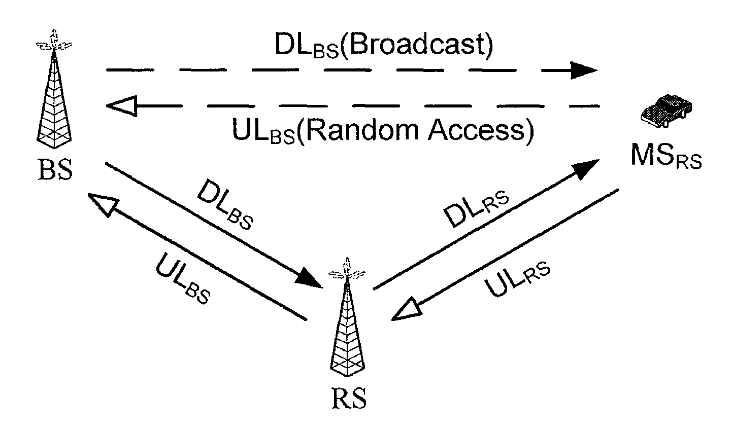
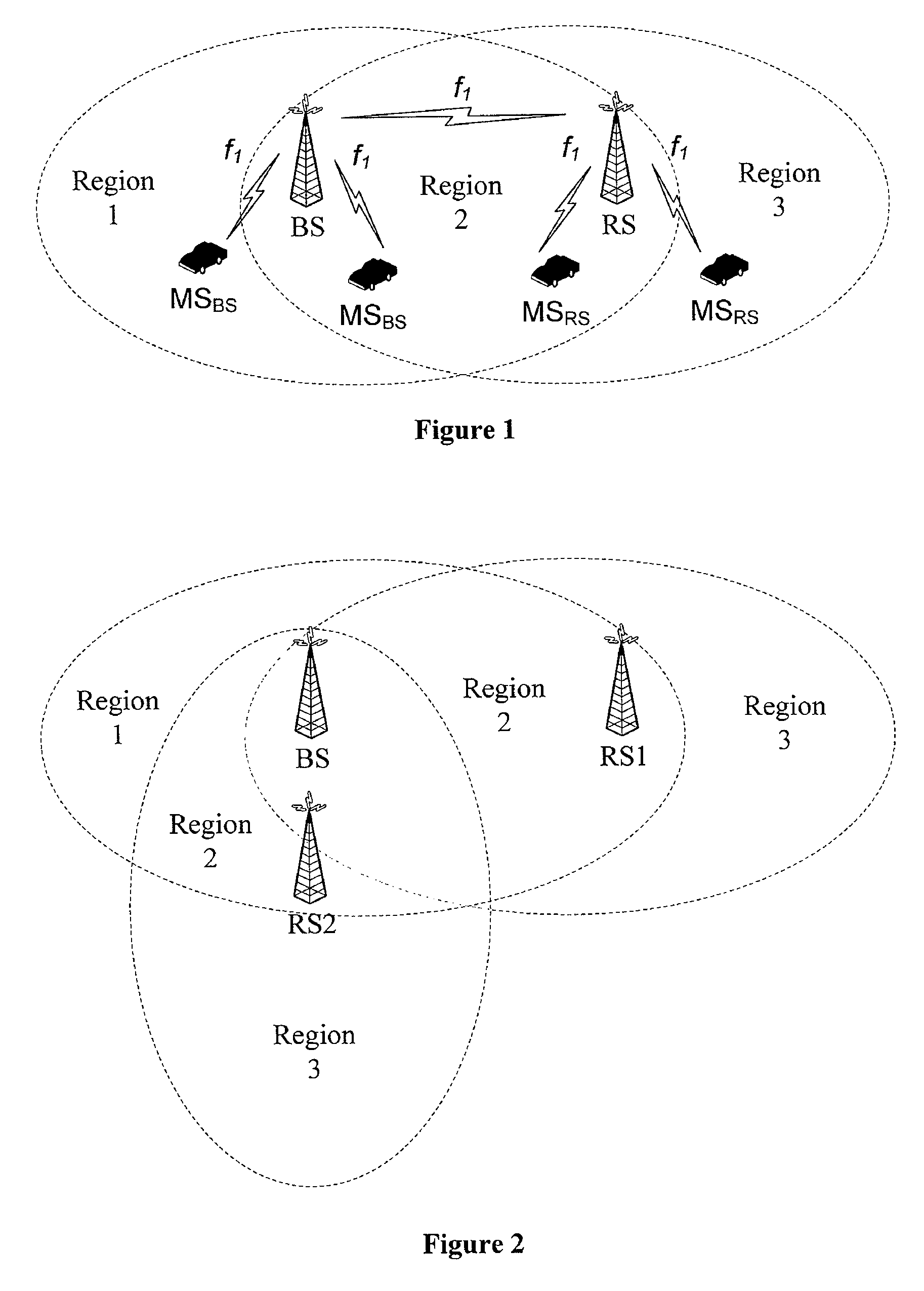
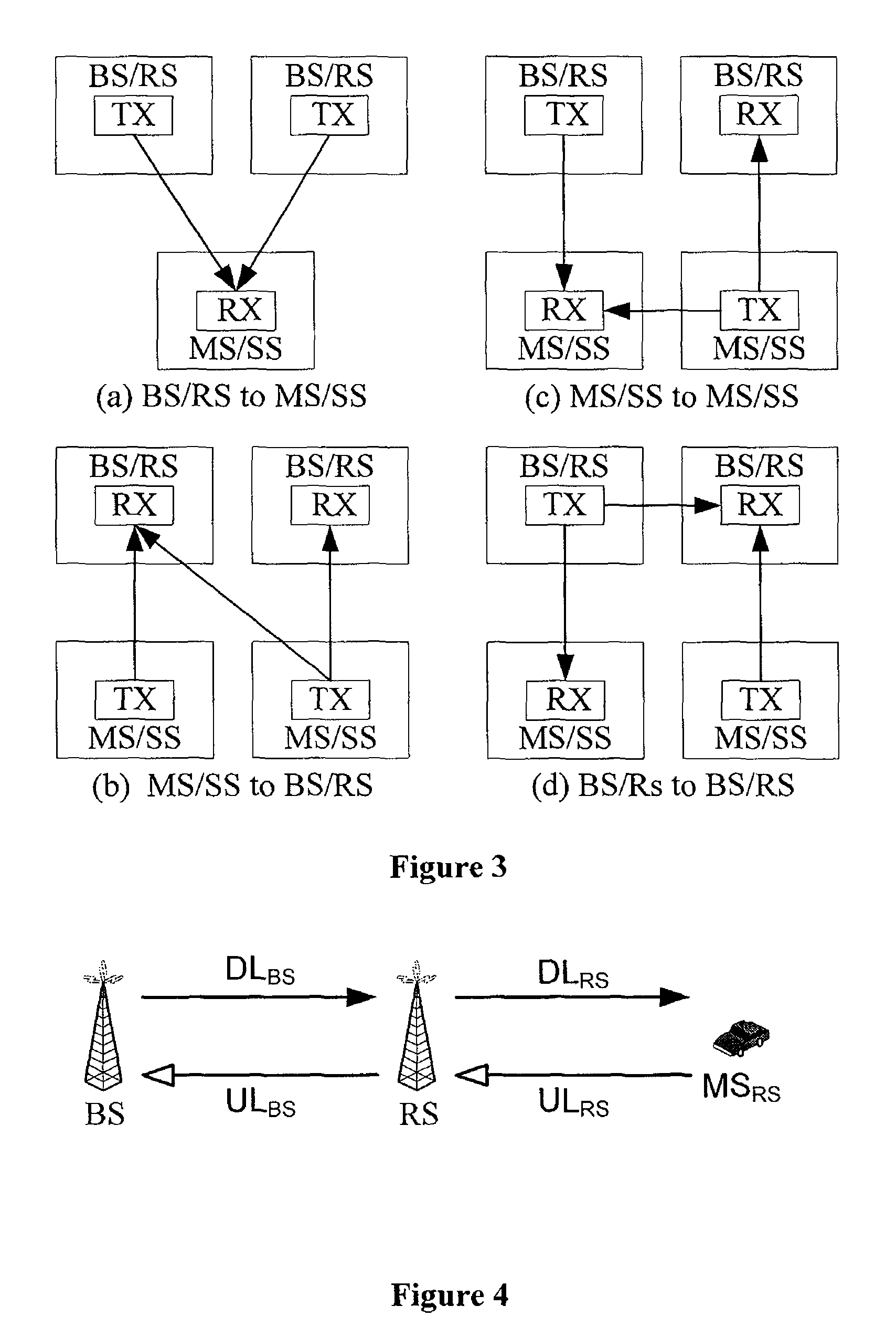
[0005]The invention is to provide a wireless relay communication system and method, to implement the relay communication between a BS and a subscriber terminal (e.g. an SS or MSS), to thereby broaden the coverage of the BS and the throughput of the subscriber terminal.
[0104]As can be seen from the above solutions of the invention, the wireless relay communication system supports an advanced relay communication mode. In other words, an MSS / SS may access a BS via the relay of an RS, thereby broadening the effective coverage of the BS, and improving the throughput of the MSS / SS. Moreover, the uplink and downlink sub-frames in the relay communication are arranged appropriately, thereby effectively preventing various interferences that may occur in the wireless relay communication.

Problems solved by technology

The entire coverage of a network is limited because of the limited coverage of base stations (BSs).
This may bring adverse affect on the information processing performance for the subscriber stations, thereby resulting in a decrease in the throughput of the subscriber stations, and an adverse affect on the communication performance of the entire network.

Method used


Image

  • Wireless relay communication system and method
  • Wireless relay communication system and method
  • Wireless relay communication system and method

Examples


first embodiment

[0204]FIGS. 5 and 6 illustrate the physical layer frame structures of BS and RS according to the invention. FIG. 5 shows the case of a single RS, and FIG. 6 shows the case of multiple RSs.

[0205]The black blocks in downlink frame DLBS of BS and downlink frame DLRS of RS represent DL Header Slots. The black blocks in uplink frame ULBS of BS and uplink frame ULRS of RS represent UL Contention Slots.

[0206]The white slender block in downlink frame DLRS of RS represents a UL Contention TX Slot. The time slot RX represented by a white slender block in uplink frame ULRS of RS is a DL Header RX Slot.

[0207]The timeslot TX in downlink frame DLBS of BS is a DL Interference Slot, for BS downlink coverage of region 2. The timeslot RX in uplink frame ULBS of BS is a UL Interference Slot, for BS uplink coverage of region 2.

[0208]The timeslot TX in downlink frame DLRS of RS is a DL Interference Slot, for RS downlink coverage of region 2. The timeslot RX in uplink frame ULRS of RS is a UL Interferenc...

second embodiment

[0212]FIG. 7 illustrates the physical layer frame structures of BS and RS according to of the invention.

[0213]As shown in FIG. 7, the UL Contention TX Slot of RS appears once every two frames. For example, the UL Contention TX Slot of RS appears in the downlink frame DLRS of Frame N−1, Frame N+1, Frame N+3.

[0214]The DL Relay Zone of BS and the UL Relay Zone of BS may be arranged in different frames. For example, the DL Relay Zone of BS may be arranged at the end of the downlink frame DLBS of FrameN. The DL Relay Zone of RS may be arranged at the header of the uplink frame ULRS of FrameN, followed by a UL Contention Slot. The UL Relay Zone of BS may be arranged to follow the UL Contention Slot of the uplink frame ULBS of Frame N+1.

[0215]The timeslots of DL Relay Zone of BS have one-to-one correspondence with those of DL Relay Zone of RS, and the timeslots of UL Relay Zone of BS have one-to-one correspondence with those of UL Relay Zone of RS. An MS does not arrange any receiving or t...

third embodiment

[0225]FIG. 8 illustrates the physical layer frame structures of BS and RS according to the invention, based on the above physical frames, of BS and RS, including the downlink non-interference timeslots and the uplink non-interference timeslots.

[0226]The black blocks in downlink frame DLBS of BS and downlink frame DLRS of RS represent DL Header Slots. The black blocks in uplink frame ULBS of BS and uplink frame ULRS of RS represent UL Contention Slots.

[0227]The time slot TX represented by a white slender block in downlink frame DLRS of RS represents a UL Contention TX Slot. The time slot RX represented by a white slender block in uplink frame ULRS of RS is a DL Header RX Slot.

[0228]The timeslot TX1 in downlink frame DLBS of BS is a DL Non-Interference Slot, for the downlink coverage of BS including region 1. The timeslot TX in downlink frame DLBS of BS is a DL Interference Slot, for BS downlink coverage of region 2. The timeslot RX1 in uplink frame ULBS of BS is a UL Non-Interference...


PUM


Abstract

A wireless relay communication system and method are provided. The system includes a BS, at least one RS and subscriber terminals. The method includes: configuring a downlink relay zone and an uplink relay zone in downlink sub-frame and uplink sub-frame of physical layer frame structure of a BS, respectively, configuring a downlink relay zone and an uplink relay zone in uplink sub-frame and downlink sub-frame of physical layer frame structure of an RS, respectively, to define one or more combinations of OFDMA symbols and relay subchannels or relay timeslots for communication between the RS and BS; performing relay communication between the BS, the RS and a subscriber station. In the invention, an advanced relay mode is supported, i.e. an MSS / SS may access BS via the relay of RS, thereby broadening the effective coverage of BS, and improving the throughput of MSS / SS.

Description

CROSS-REFERENCE TO RELATED APPLICATIONS[0001]This application is a continuation of International Patent Application No. PCT / CN2006 / 002575, filed Sep. 29, 2006, which claims priority to Chinese Patent Application Nos. 200510106291.3, 200510114596.9, 200510117477.9, 200510117478.3, 200510117222.2, 200510115918.1, and 200510115917.7, filed Sep. 30, 2005, Oct. 26, 2005, Oct. 31, 2005, Oct. 31, 2005, Nov. 1, 2005, Nov. 11, 2005, and Nov. 11, 2005, respectively, all of which are hereby incorporated by reference in their entirety.FIELD OF THE INVENTION[0002]The invention relates to the field of wireless communications, and in particular, to a wireless relay communication system and method.BACKGROUND OF THE INVENTION[0003]The broadband wireless access standard IEEE 802.16 mainly includes two versions, i.e., a fixed broadband wireless access standard IEEE 802.16-2004 and a mobile broadband wireless access standard IEEE 802.16e. 802.16-2004 defines two types of network elements, i.e. Base sta...

Claims


Application Information

Patent Timeline
Patent Type & Authority Patents(United States)
IPC IPC(8): H04B7/14H04B7/212H04J1/10H04J3/08H04W4/00H04W16/26H04W88/08
CPCH04B7/15557H04L5/1469H04L5/0007H04W16/26H04W88/085
Inventor ZHENG, RUOBIN
Owner HUAWEI TECH CO LTD
Why Eureka
Try Eureka