
Modular furniture system

a modular furniture and furniture technology, applied in the field of modular furniture systems, can solve the problems of inability to meet exact or uniform raw material specifications, inability to accurately and uniformly manufacture products, and inability to ensure the accuracy of raw material specifications, etc., to achieve the effect of convenient assembly and secure assembly of products

Inactive Publication Date: 2012-07-17
KITTRICH
View PDF11 Cites 12 Cited by
  • Summary
  • Abstract
  • Description
  • Claims
  • Application Information

AI Technical Summary

Benefits of technology

[0013]Therefore, it is an objective of the present invention to provide a modular furniture system that may be manufactured entirely from planar material of uniform thickness, that may be assembled without tools or fasteners, that may be reversible, and that may be re-configured into different pieces of furniture.
[0016]While an obvious solution would be to engineer close fit tolerances into the design, thereby limiting the acceptable range of dimensional variations, it is not practical to do so because this will tend to result in higher costs due to lower raw material yield and higher part rejection due to more manufactured parts being beyond the acceptable dimensional limits. It is nearly always beneficial to engineer the greatest possible loose fit tolerances into the design to maximize yield and minimize costs.
[0027]8. Improved joint designs provide low-effort, ease of assembly, yet still yield securely assembled product.

Problems solved by technology

In real life, however, raw material specifications cannot be relied upon to be exact or uniform, and manufacturing processes can be imprecise and introduce dimensional variations in manufactured product because of such factors as cutter sharpness, machine repeatability, sanding, routing and finishing variations, to name a few.
These variations in raw material specifications and manufacturing precision can result in manufactured product that does not meet exact specifications.
In these cases, assembly of the product can be difficult, or the assembled product can be less secure and solid than desired.
However, under conditions other than these extreme conditions, loose fit tolerances typically result in joints that are loose and an assembled product that is less than secure.

Method used


Image

  • Modular furniture system
  • Modular furniture system
  • Modular furniture system

Examples


Embodiment Construction

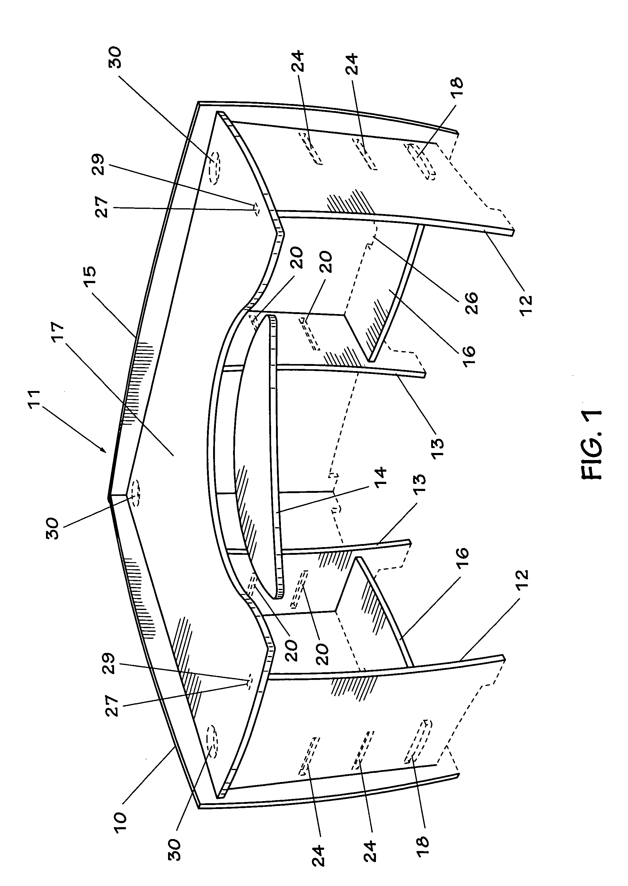
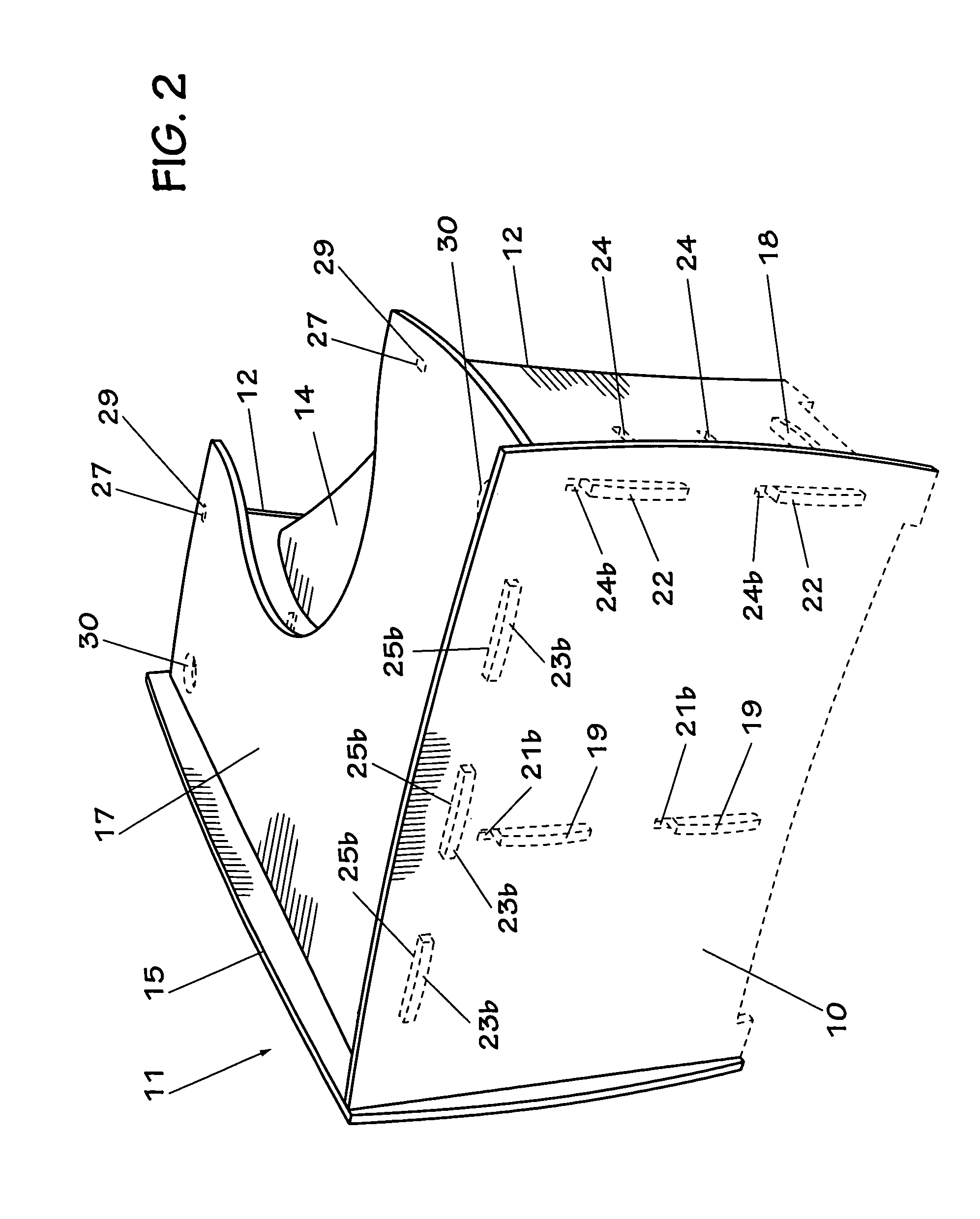
[0078]Referring to FIG. 1 in the drawings, a desk 11 made in accordance with the modular furniture system of the present invention is illustrated. Desk 11 is an example of the type of furniture that can be assembled with from the interlocking components of the present invention. As explained herein, the modular furniture system of the present invention allows a user to assemble, disassemble, and reconfigure various interchangeable and reversible components into a large variety of pieces of furniture, such as tables, generally rectangular desks, corner desks, desk returns, desk extensions, desk bridges, hutches, bookcases, end tables, and others.

[0079]Desk 11 is a corner desk interlockingly assembled from a plurality of wide vertical side supports 12, a plurality of narrow vertical side supports 13, a long vertical rear support 15, a short vertical rear support 10, and a desk work surface 17. Optionally, desk 11 may include a plurality of shelves 16 and a keyboard tray 14. Each wide ...


PUM


Abstract

A modular furniture system having planar vertical components having slots and / or tabs, and planar horizontal components having slots and / or tabs, wherein the vertical components and the horizontal components releasably and interlockingly mate with each other to form a plurality of different pieces of furniture.

Description

CLAIM OF PRIORITY[0001]This continuation-in-part application claims the benefit of U.S. patent application Ser. No. 09 / 753,799, filed 2 Jan. 2001 now U.S. Pat. No. 6,769,369, entitled “Modular Furniture System,” which claims the benefit of U.S. Provisional Patent Application Ser. No. 60 / 173,960, filed 30 Dec. 1999, entitled “Modular Desk System.” This continuation-in-part application is incorporated herein as if fully set forth.BACKGROUND OF THE INVENTION[0002]1. Field of the Invention[0003]The present invention relates to interlocking modular furniture. More particularly, the present invention relates to an assembly method for ready-to-assemble furniture made from planar material.[0004]2. Background of the Invention[0005]The internet has caused an incredible growth in the number of new businesses established to take advantage of products and services that can be sold and distributed over the internet. These businesses typically begin as small, private businesses that require but ca...

Claims


Application Information

Patent Timeline
Patent Type & Authority Patents(United States)
IPC IPC(8): A47B91/00
CPCA47B3/06A47B47/042A47B2230/0085
Inventor BRANDENBERG, CARL BROCK
Owner KITTRICH
Learn More