Apparatus and method for providing an inerting gas during soldering

a technology of inerting gas and soldering, which is applied in the direction of soldering apparatus, manufacturing tools, non-electric welding apparatus, etc., can solve the problems of dross formation, bridges, or other defects in solder joints, and the cost of lead-free solder is normally much higher than that of conventional tin-lead solder, and achieves cost-effective effects

Active Publication Date: 2012-07-17
AIR PROD & CHEM INC
View PDF31 Cites 8 Cited by
  • Summary
  • Abstract
  • Description
  • Claims
  • Application Information

AI Technical Summary

Problems solved by technology

The presence of a dross and / or an oxide layer is known to cause skips, bridges, or other defects in solder joints.
Furthermore, the cost of a lead-free solder is normally much higher than that of the conventional tin-lead solder, and the economy loss associated with solder waste by dross formation is more significant than that of lead-free wave soldering.
In addition, the wetting performance of a lead-free solder is intrinsically poor compared with that of the conventional tin-lead solder.
The porous tubes, however, become easily clogged by solder splashing or flux vapor condensation during the wave soldering process.
Present methods of cleaning the diffuser tubes such as, for example, using ultrasonic baths filled with cleaning solutions, are extremely difficult and time consuming.
The cleaning of these tubes must be performed on a regular basis and can cause physical damage to the tubes.
This increases the overall cost to the end-user.

Method used


Image

  • Apparatus and method for providing an inerting gas during soldering
  • Apparatus and method for providing an inerting gas during soldering
  • Apparatus and method for providing an inerting gas during soldering

Examples


example 1

Effect of Pore Size of Porous tube on Gas Flow Pattern

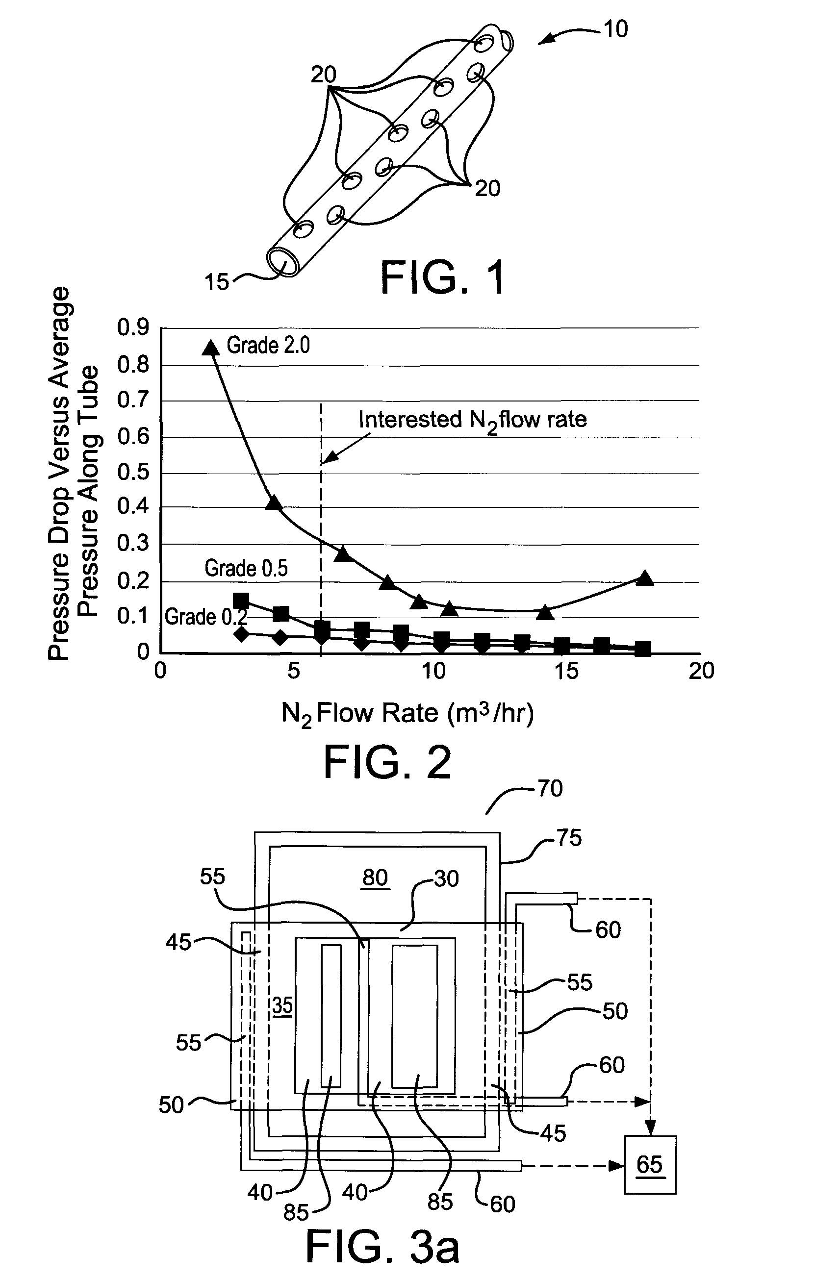
[0060]Three diffusers or porous tubes with three different grade levels as listed in the following table were tested. A lower grade represents a smaller pore size and porosity of the diffuser. The test was conducted by flowing house N2 into each seamless porous tube and measuring pressures at the upstream (Pup) and downstream (Pdown) of each diffuser for a given N2 flow rate. The pressure drop (ΔP) along the diffuser is determined as follows:

ΔP=Pup−Pdown

[0061]The average pressure along the diffuser was then calculated as:

Pave=(Pup+Pdown) / 2

[0062]When ΔP / Pave is much less than 1, the gas flow out of the diffuser tube can be considered as in a laminar flow pattern. In contrast, when ΔP / Pave is close to 1, a turbulent gas flow is normally dominant. For certain embodiments, it is preferred that the porous tube provides a laminar gas flow pattern.

[0063]As indicated in Table I and FIG. 2, at the interested N2 flow rate the ΔP / Pave of 0...

example 2

Effect of Heated Diffuser for N2 Inerting in Wave Soldering

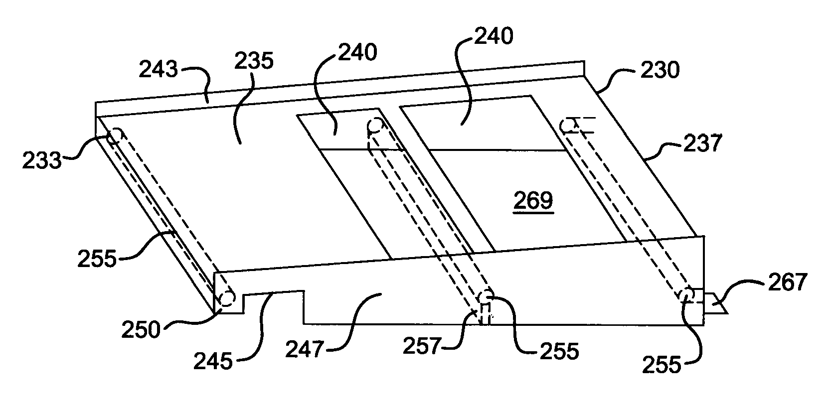
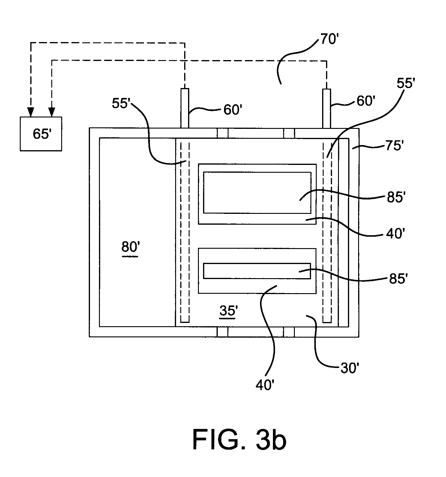
[0065]In this example, at least one of the porous tubes is located between the two soldering waves and has a metal fin that is inserted into the molten solder reservoir, so that the temperature of the porous tube diffuser can be maintained above the solder's melting point. This heated diffuser can avoid potential clogging problems such as by solder splashing / solidification and by flux vapor condensation on diffuser surface. An example of the configuration used for this experiment is shown in FIG. 9.

[0066]FIG. 19 provides the results of O2 concentrations around the solder reservoir in positions 1 through 8 designated in FIG. 18 with a static board on top of the solder reservoir and without the top cover (such as that shown in FIG. 5) and FIG. 20 repeats the O2 analysis with the top cover and ventilation on (such as that shown in FIG. 5). Based upon visual observation, any soldering splash on the porous tube surface could not ...

example 3

Application of Non-Stick Porous Sleeve to Center Diffuser Tube

[0067]In this example, at least one of the porous tubes is located between the two soldering waves and has a metal fin that is inserted into the molten solder reservoir, so that the temperature of the porous tube diffuser can be maintained above the solder's melting point. This heated diffuser can avoid potential clogging problems such as by solder splashing / solidification and by flux vapor condensation on diffuser surface. An example of the configuration used for this experiment is shown in FIG. 9.

[0068]The center diffuser tube was covered with a sleeve made of ePTFE (expandable polytetrafluoroethylene). The ePTFE was formed in a tube shape and white color made by Phillips Scientific Inc. with item number TB3000. The porous tube is expandable only along the length of the tube, but non-expandable along the diameter direction. The material can survive 315° C. and has an average pore size around 2 to 10 micron meters. The w...


PUM

PropertyMeasurementUnit
pore sizeaaaaaaaaaa
temperatureaaaaaaaaaa
temperaturesaaaaaaaaaa

Abstract

Described herein is an apparatus and method for providing an inerting gas during the application of soldering to a work piece. In one aspect, there is provided an apparatus that is placed atop of a solder reservoir and comprises a plurality of porous tubes that are in fluid communication with an inerting gas. In another aspect, there is provided a method for providing an inerting gas to a wave soldering apparatus comprising the steps of, among other things, placing an apparatus atop at least one edge of the solder reservoir wherein the apparatus comprises a plurality of tubes comprising one or more openings in fluid communication with an inerting gas source. In a further aspect, at least one of the tubes comprises a non-stick coating or is comprised of a porous non-stick material such as a sleeve.

Description

CROSS-REFERENCE TO RELATED APPLICATIONS[0001]This application claims the priority benefit of the following applications: U.S. Provisional Application No. 61 / 313,376, filed 12 Mar. 2010; U.S. Provisional Application No. 61 / 313,372, filed 12 Mar. 2010; U.S. Provisional Application No. 61 / 321,011 filed 5 Apr. 2010; U.S. Provisional Application No. 61 / 320,939 filed 5 Apr. 2010; U.S. Provisional Application No, 61 / 323,607 filed 13 Apr. 2010; and U.S. Provisional Application No. 61 / 365,607 filed 19 Jul. 2010.BACKGROUND OF THE INVENTION[0002]Described herein is an apparatus and a method for providing an inerting gas during soldering. More specifically, described herein is an apparatus and a method for providing an inerting gas during wave soldering using nitrogen and / or other inerting gas.[0003]Work pieces such as printed wiring boards or circuit boards have increasingly smaller wettable surfaces that need to be solder coated and joined. Typical operations for wave soldering involve a sold...

Claims


Application Information

Patent Timeline
Patent Type & Authority Patents(United States)
IPC IPC(8): B23K31/02
CPCB23K3/0653B23K3/08B23K3/085
Inventor DONG, CHUN CHRISTINEARSIANIAN, GREGORY KHOSROVGHOSH, RANAJITWANG, VICTORWU, JERRY
Owner AIR PROD & CHEM INC
Why Eureka
Try Eureka