Scanning irradiation device of charged particle beam

a charged particle and scanning irradiation technology, applied in the field of scanning irradiation devices of charged particle beams, can solve the problems of difficult to give sufficient radiation dose to the irradiation target, and the rotation gantry becomes an expensive irradiation devi

Active Publication Date: 2012-07-17
SHIZUOKA PREFECTURE
View PDF9 Cites 43 Cited by
  • Summary
  • Abstract
  • Description
  • Claims
  • Application Information

AI Technical Summary

Benefits of technology

[0008]An object of the present invention is to solve the foregoing problem and to provide an inexpensive scanning irradiation device of a charged particle beam without using a rotating gantry.
[0011]According to a scanning irradiation device of a charged particle beam of the present invention, a direction of patient's recumbent position on a treatment bed, thereby making it possible to irradiate at any angle of 360 degrees relative to a patient's body axis, whereby multiple field irradiation can be performed at any irradiation angle even without using a gantry.
[0013]In addition, according to a scanning irradiation device of a charged particle beam of the present invention, a backrest of a sitting position treatment bed can be inclined back and forth at a range of −45 degrees to +45 degrees, thereby making it possible to irradiate at any angle above a horizontal level relative to head and neck, whereby an irradiation device capable of performing multiple field irradiation of the head and neck can be supplied inexpensively.

Problems solved by technology

When important organs which do not have to be irradiated are located in the vicinity of the irradiation target, there is a difficult case to give sufficient radiation dose to the irradiation target by only irradiation from one direction while suppressing the radiation dose to the important organs.
The rotating gantry is of the rotational structure having a diameter of approximately 10 m; and therefore, the rotating gantry becomes an expensive irradiation device.

Method used


Image

  • Scanning irradiation device of charged particle beam
  • Scanning irradiation device of charged particle beam
  • Scanning irradiation device of charged particle beam

Examples


embodiment 1

Preferred Embodiment 1

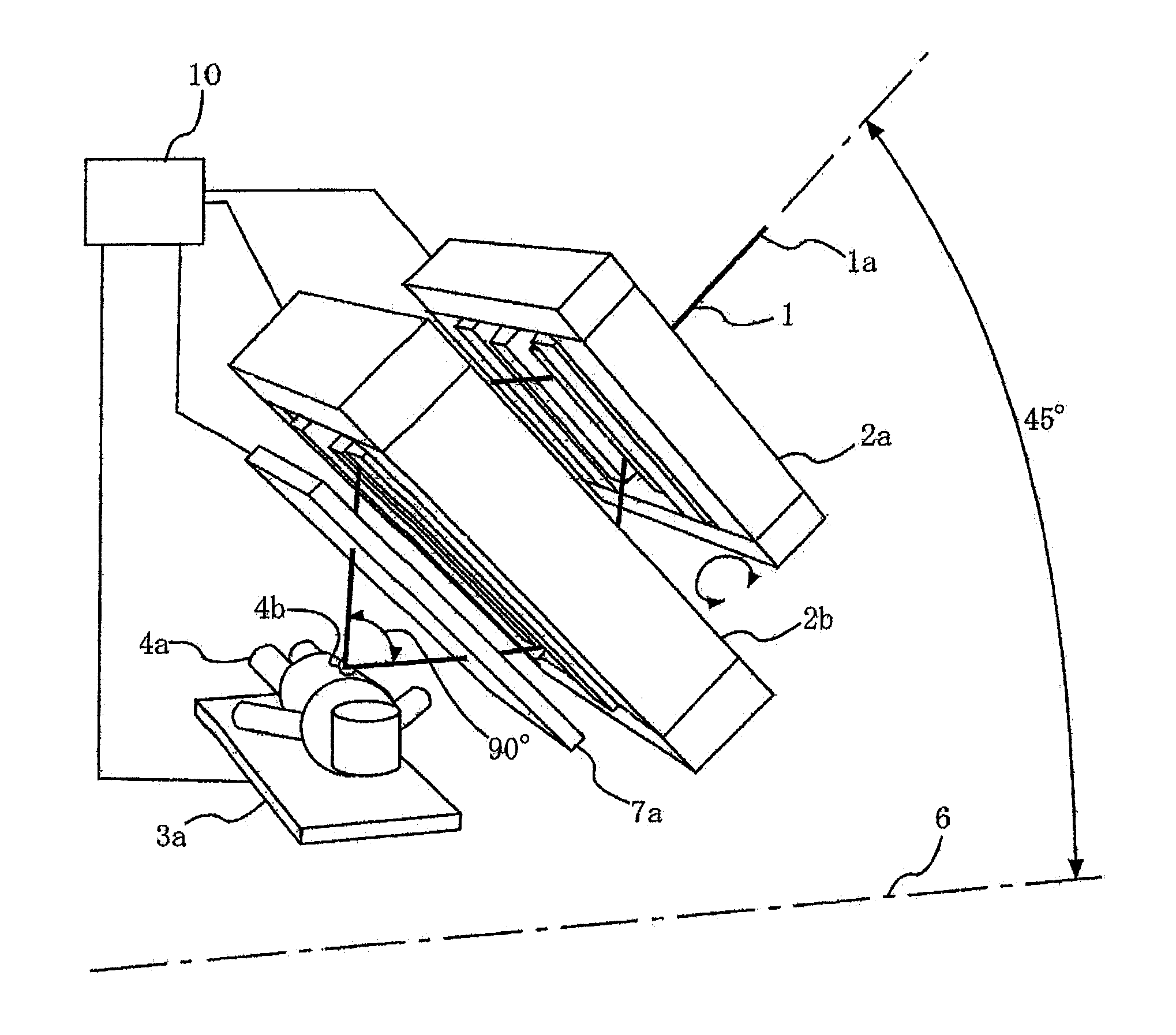
[0025]FIG. 1 is a configuration diagram showing a scanning irradiation device of a charged particle beam according to a preferred embodiment 1 of the present invention. A charged particle beam (referred to as beam) 1, which is taken out from an accelerator and is transported via a group of electromagnets such as quadrupole electromagnets and deflection electromagnets, is made incident from an incident beam axis angle of approximately 45 degrees relative to a floor (horizontal direction) 6. A first scanning electromagnet 2a deflects the beam 1 at any angle of a range of −45 degrees to +45 degrees (its range may be exceeded) relative to an incident beam axis 1a. A second scanning electromagnet 2b is arranged at the lower stream of the first scanning electromagnet 2a, has a beam deflection surface which is located on the same surface as that of the first scanning electromagnet 2a, and deflects the beam 1 at any angle of a range of −90 degrees to +90 degrees (its r...

embodiment 2

Preferred Embodiment 2

[0031]In a preferred embodiment 1, the recumbent position treatment bed 3a is kept in a horizontal position; however, if the recumbent position treatment bed is located in a range of approximately −15 degrees to +15 degrees around the body axis of the patient 4a, it is easy to fix the patient so as not to be slid down, and the recumbent position treatment bed may be inclined. FIG. 3 is a configuration diagram showing a scanning irradiation device of a charged particle beam according to a preferred embodiment 2. Incidentally, the same reference numerals are identical or equivalent portions in the respective drawings and their description will not be repeated. As shown in FIG. 3, a charged particle beam 1 is made incident from an incident beam axis angle of approximately 45 degrees relative to a floor (horizontal direction) 6. A first scanning electromagnet 2a deflects the beam 1 at any angle of a range of −30 degrees to +30 degrees (its range may be exceeded) re...

embodiment 3

Preferred Embodiment 3

[0036]In the preferred embodiments 1 and 2, the description is made about the case where the incident beam axis 1a is only one direction; however, as shown in FIG. 4, there may be provided incident beam axes in two directions, that is, two systems. FIG. 4 is a configuration diagram showing a scanning irradiation device of a charged particle beam according to a preferred embodiment 3. In a first system, a first incident beam axis 1 is made incident from a first incident beam axis angle of approximately 22.5 degrees relative to a floor (horizontal direction) 6. A first scanning electromagnet 2a deflects the beam 1 at any angle of a range of −22.5 degrees to +22.5 degrees (its range may be exceeded) relative to a first incident beam axis 1a. A second scanning electromagnet 2b is arranged at the lower stream of the first scanning electromagnet 2a, has a beam deflection surface which is located on the same surface as that of the first scanning electromagnet 2a, and ...


PUM

PropertyMeasurementUnit
axis angleaaaaaaaaaa
deflection angleaaaaaaaaaa

Abstract

An inexpensive scanning irradiation device of a particle beam is obtained without using a rotating gantry. A first scanning electromagnet and a second scanning electromagnet, whose deflection surfaces of the particle beam are the same, and which bend the particle beam having an incident beam axis angle of approximately 45 degrees relative to a horizontal direction in reverse directions to each other; an electromagnet rotation driving mechanism which integrates the first and the second scanning electromagnets and rotates these scanning electromagnets around the incident beam axis; and a treatment bed are provided. The particle beam deflected by the first and the second scanning electromagnets can be obtained at a range of −45 degrees to +45 degrees in deflection angle from an incident beam axis direction.

Description

BACKGROUND OF THE INVENTION[0001]1. Field of the Invention[0002]The present invention relates to a scanning irradiation device of a charged particle beam, in which a charged particle beam emitted from an accelerator is deflected by a first scanning electromagnet and a second scanning electromagnet and is irradiated to an irradiation target.[0003]2. Description of the Related Art[0004]A scanning irradiation device of a charged particle beam in known particle beam therapy systems includes an accelerator which emits a charged particle beam (for example, beam of electron, proton, and heavy ion); a group of electromagnets such as quadrupole electromagnets and deflection electromagnets which transport abeam taken out from the accelerator; two scanning electromagnets (scanning electromagnet pair) in which beam deflection surfaces are located on the same surface, and excited in opposite polarity to each other; a magnet rotation driving mechanism which rotates the scanning electromagnet pair...

Claims


Application Information

Patent Timeline
Patent Type & Authority Patents(United States)
IPC IPC(8): G01K1/08H01J3/26H01J3/14
CPCA61N5/1042A61N5/1043A61N5/1078G21K1/093G21K5/00A61N5/1084A61N2005/1087
Inventor TAJIRI, SHINYAYAMAMOTO, YUICHIPU, YUEHUYAMASHITA, HARUO
Owner SHIZUOKA PREFECTURE
Why Eureka
Try Eureka