Fuel injector with built-in fuel pressure sensor

a fuel pressure sensor and injector technology, applied in the field of fuel injectors, can solve the problems of insufficient to satisfy the required accuracy of determining the fuel pressure change, and the increase in the accuracy of determining the pressure chang

Active Publication Date: 2012-07-17
DENSO CORP
View PDF15 Cites 14 Cited by
  • Summary
  • Abstract
  • Description
  • Claims
  • Application Information

AI Technical Summary

Benefits of technology

[0012]Specifically, the fuel pressure sensor is built in the fuel injector. In other words, the fuel pressure sensor is located closer to the spray hole than the prior art structure, as disclosed in the above publication, thus resulting in increased accuracy in measuring a change in pressure of the fuel arising from the spraying of the fuel from the spray hole.
[0013]In the preferred mode of the invention, the fuel injector further comprises a signal wire which is joined to the fuel pressure sensor and through which the signal, as produced by the fuel pressure sensor, is outputted outside the body and a fuel drain path through which a portion of the fuel is drained outside the body at a pressure lower than that in the fuel supply path. The signal wire is disposed in the fuel drain path. This permits a hermetical seal required to avoid the leakage of the fuel from a wire outlet hole to be achieved by a simple structure because it is required merely to avoid the leakage of the low-pressure fuel.

Problems solved by technology

For instance, in the case where a change in pressure of the fuel arising from the spraying of the fuel from the fuel injector (which will also be referred to as a fuel pressure change below) is measured using a fuel pressure sensor installed directly in a common rail (i.e., a fuel accumulator), it will be somewhat absorbed within the common rail, thus resulting in a decrease in accuracy in determining such a pressure change.
The fuel pressure change, however, usually somewhat attenuates in the high-pressure pipe.
The fuel pressure sensor, as disclosed in the above publication, disposed in the joint between the common rail and the high-pressure pipe is, therefore, insufficient to satisfy the required accuracy of determining the fuel pressure change.

Method used


Image

  • Fuel injector with built-in fuel pressure sensor
  • Fuel injector with built-in fuel pressure sensor
  • Fuel injector with built-in fuel pressure sensor

Examples


Embodiment Construction

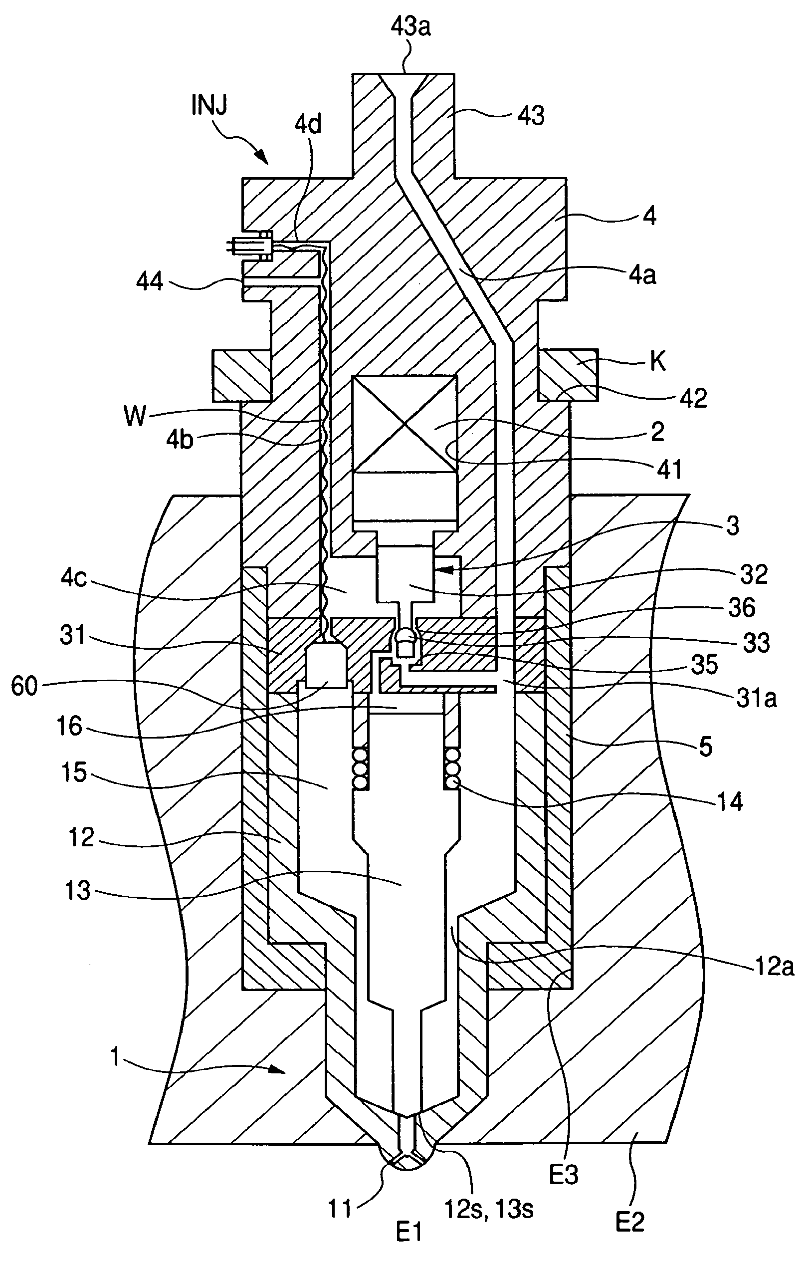
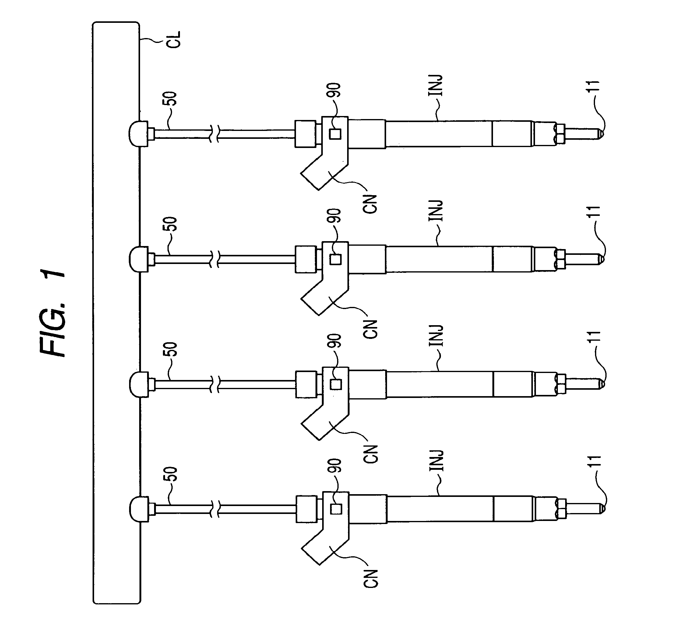
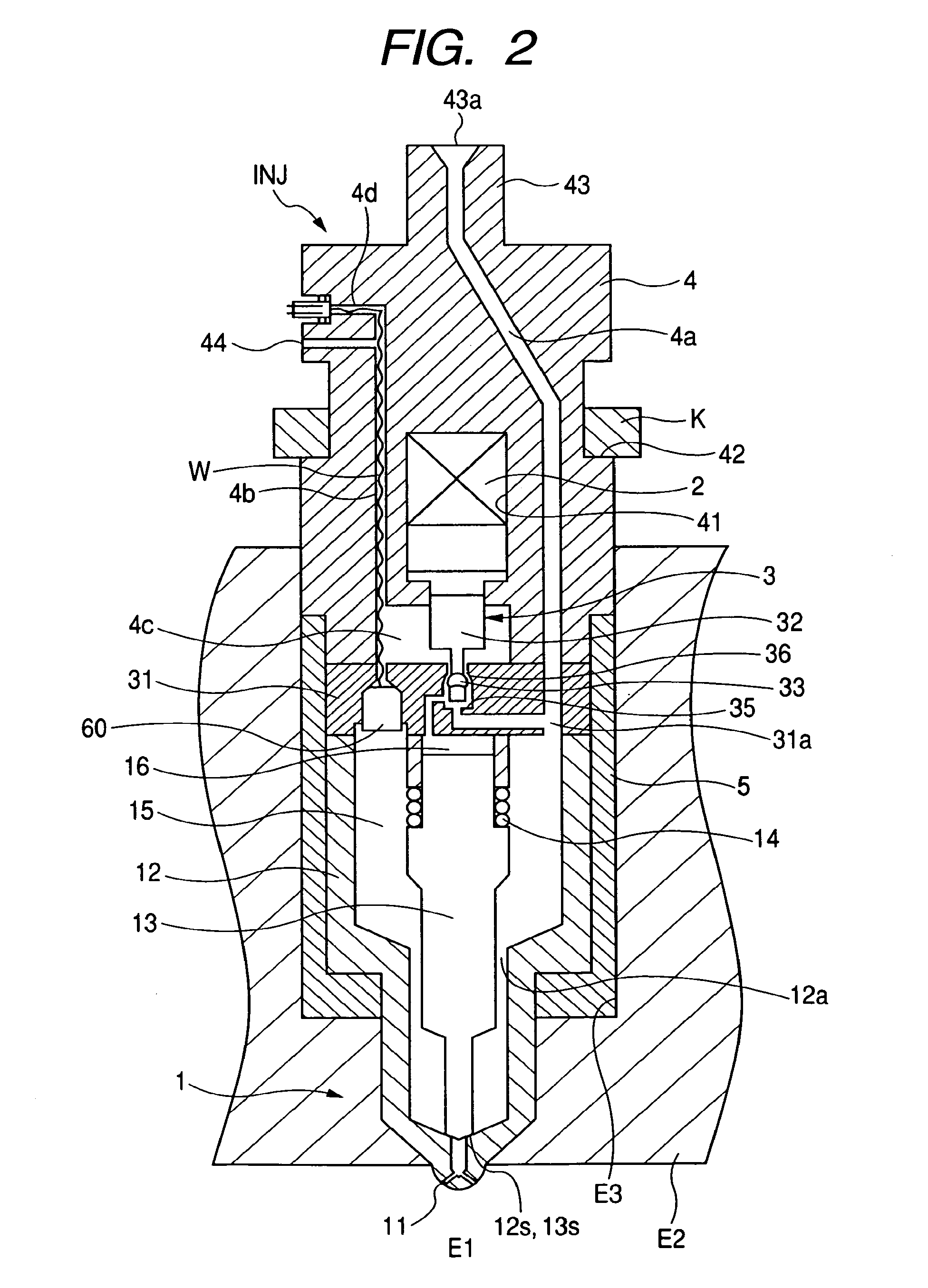
[0022]Referring to the drawings, wherein like reference numbers refer to like parts in several views, particularly to FIG. 1, there is shown fuel injectors INJ according to the invention which are joined to a common rail CL (i.e., a fuel accumulator), as usually used in an automotive fuel injection system. FIG. 2 is a longitudinal sectional view which shows an internal structure of each of the injectors INJ. FIG. 3 is an enlarged view of FIG. 2.

[0023]Each of the injectors INJ, as illustrated in FIGS. 1 and 2, works to spray the fuel, as supplied from the common rail CL, into a corresponding one of combustion chambers E1 of the internal combustion engine. The injectors INJ are installed in a cylinder head E2 of the engine.

[0024]The engine, as referred to herein, is an automotive in-line four-cylinder four-stroke reciprocating diesel engine in which high-pressure light fuel is to be injected directly into the combustion chamber E1 at an atmospheric pressure of 1000 or more. The common...


PUM


Abstract

A fuel injector for an internal combustion engine is provided which has a fuel supply path and a nozzle chamber. The fuel supply path extends a spray hole. The nozzle chamber is defined in the fuel supply path. A nozzle is disposed within the nozzle chamber to establish or block a fluid communication between the fuel supply path and the spray hole. A fuel pressure sensor is installed in the fuel injector so as to be exposed to the fuel in the nozzle chamber. Specifically, the fuel pressure sensor is located closer to the spray hole than a prior art structure in which the fuel pressure sensor is installed in a fuel supply pipe, thus resulting in increased accuracy in measuring a change in pressure of the fuel arising from the spraying of the fuel from the spray hole.

Description

CROSS REFERENCE TO RELATED DOCUMENT[0001]The present application claims the benefit of Japanese Patent Application No. 2008-86992 filed on Mar. 28, 2008, the disclosures of which are incorporated herein by reference.BACKGROUND OF THE INVENTION[0002]1. Technical Field of the Invention[0003]The present invention relates generally to a fuel injector to be installed in an internal combustion engine to spray fuel thereinto, and more particularly to such a fuel injector which has installed therein a fuel pressure sensor working to measure a change in pressure of fuel arising from the spraying of the fuel into the engine accurately.[0004]2. Background Art[0005]In order to ensure the accuracy in controlling output torque of internal combustion engines and the quantity of exhaust emissions therefrom, it is essential to control a fuel injection mode such as the quantity of fuel to be sprayed from a fuel injector or the injection timing at which the fuel injector starts to spray the fuel. For ...

Claims


Application Information

Patent Timeline
Patent Type & Authority Patents(United States)
IPC IPC(8): G06F19/00F02M69/46F02M55/02F02M61/16
CPCF02M57/005F02M65/003G01L9/085G01L23/10F02D2200/0602F02M2200/24F02M2200/21F02M2200/248F02M47/027F02M51/005F02M55/002F02M2200/247F02M2200/8007
Inventor KONDO, JUNTAGUCHI, TOORU
Owner DENSO CORP
Why Eureka
Try Eureka