Valve for wind instrument

a valve and wind instrument technology, applied in the field of wind instruments and musical instruments, can solve the problems of adversely affecting the “blowing power” of musicians, the valve passage itself involved some rather sharp bends, etc., and achieves the effects of improving intonation and sound quality, improving volumetric flow, and improving laminar flow

Active Publication Date: 2012-07-24
WILK MARTIN A
View PDF25 Cites 3 Cited by
  • Summary
  • Abstract
  • Description
  • Claims
  • Application Information

AI Technical Summary

Benefits of technology

[0014]Advantages associated with the various uses and embodiments of the present invention include the following: sound wave paths less constricted; combination (hybrid) of piston and rotor valves; hollow piston with sheet metal rotor passage; unimpeded (from bumps) wind ways; improved response and playing characteristics (all registers) flexibility and clarity, e.g., slurring, sound response; increased energy transfer due to improved flow characteristics; reduced back-pressure or resistance in both open and actuated conditions; extra strong trough insures piston rigidity; simpler to manufacture as the balling stage is eliminated for one passage; the effective piston to casing sealing area is essentially functionally unchanged from a regular piston; one less vertical member (land or wed) to align; less vertical interval web protrusion within the valve itself; can be made with minimal changes in manufacture techniques, materials; rotor-like passage in present invention can be used for ingress or egress of the vibrating air column when the switching loop is employed; employs the valve casing as both a sealing surface and a wind way simultaneously when the piston is activated; no change in piston stroke length or felting / corking when compared to the normal valve; no change in casing appearance when this invention is in place; the inventive system piston can be refit in same manner as regular piston; less surface area on contact surface of valve, reducing friction; no change in casing or slide loops needed when converting to present invention; produces beneficial acoustical effects in a hybrid piston / rotor like passage valve. The invention may be used in conjunction with different types of valve designs including, for example, Perinet, rotary (hollow or solid), Berliner, Allen, and other hollow valve designs.
[0016]In another embodiment, the present invention provides a valve assembly designed to regulate air flow through a musical instrument. The valve assembly comprises: a) a cylindrical-shaped valve casing having openings formed therein that define at least one ingress and at least one egress through which vibrating columns of air pass; and b) a rotary valve received within the valve casing and rotatably displaceable therein, the rotary valve comprising at least one passageway having a substantially circular cross-section that mitigates distortion.
[0018]Advantages of the various embodiments of the present invention include increase in volumetric flow, improved laminar flow, improved intonation and sound quality, improved alignment, “bumpless” relatively unimpeded windways or passageways within valve bodies, and less surface area in contact with the valve casing by removing webs or lands. The invention may be used in fabricating new instruments and pistons or in retrofitting existing valve pistons. Removing webs may also alleviate leading edge issues when transitioning valves from engaged to unengaged positions as well as alignment issues. The invention has application in both piston and rotary valve applications.

Problems solved by technology

Although rotary valves allowed for fast play and addressed some playability issues, they have drawbacks.
One problem with the traditional rotary design is that sharp edges and constrictions formed in the disc deflect the vibrating air column flowing in the air passages to such a degree that the sound volume and the quality of the tone as well as the ease with which the tone can be produced are adversely affected.
And the internal valve passages themselves involved some rather sharp bends.
These constrictions or “convolutions” in the air flow path add additional resistance to the flowing air column and adversely affect musician's “blowing power” by limiting the maximum volume that a musician can obtain, and also undesirably affects tonal quality.
Yet another difficulty with known rotary valves is that even though the stationary tubing attached to the valve casing is circular in cross-section, the passages in the rotating valve piston are often ellipsoid (or, perhaps of some other shape) but not circular.
The tonal quality of the instrument is thereby adversely affected.
But the long actuating stroke and the high inertia of said valves oppose a fast playing.
A problem commonly associated with Perinet valves is that due to physical constraints associated with placing liners (or troughs or tubular material) that form the upper, middle and lower windways within the openings formed in the piston and disposing the liners within the hollow inner volume of the piston body, tradeoffs have been made that adversely affect tonal quality and volumetric capacity and laminar flow of the air column passing through the Perinet valve.
In particular, the manufacturing of the piston valve due to the size constraints within the narrow hollow piston body results in “lumps” or “bumps” being formed in at least one and typically two of the windways.
This results in less than generous space in the valve piston in which to form switching and return passages.
Unfortunately, this leads to the drawback of further constricting the amount of space available for forming the windways or passageways in the piston body.
Lumps formed as an artifact in the manufacturing process represent irregularities in the surface of the windway and cause distortion in the air column passing through the windway.
This has the unfortunate effect of increasing the severity of the lumps and limiting the volumetric capacity and flow of the valve.

Method used


Image

  • Valve for wind instrument
  • Valve for wind instrument
  • Valve for wind instrument

Examples


Embodiment Construction

[0034]The present invention will now be described in more detail with reference to exemplary embodiments as shown in the accompanying drawings. While the present invention is described herein with reference to the exemplary embodiments, it should be understood that the present invention is not limited to such exemplary embodiments. Those possessing ordinary skill in the art and having access to the teachings herein will recognize additional implementations, modifications, and embodiments, as well as other applications for use of the invention, which are fully contemplated herein as within the scope of the present invention as disclosed and claimed herein, and with respect to which the present invention could be of significant utility.

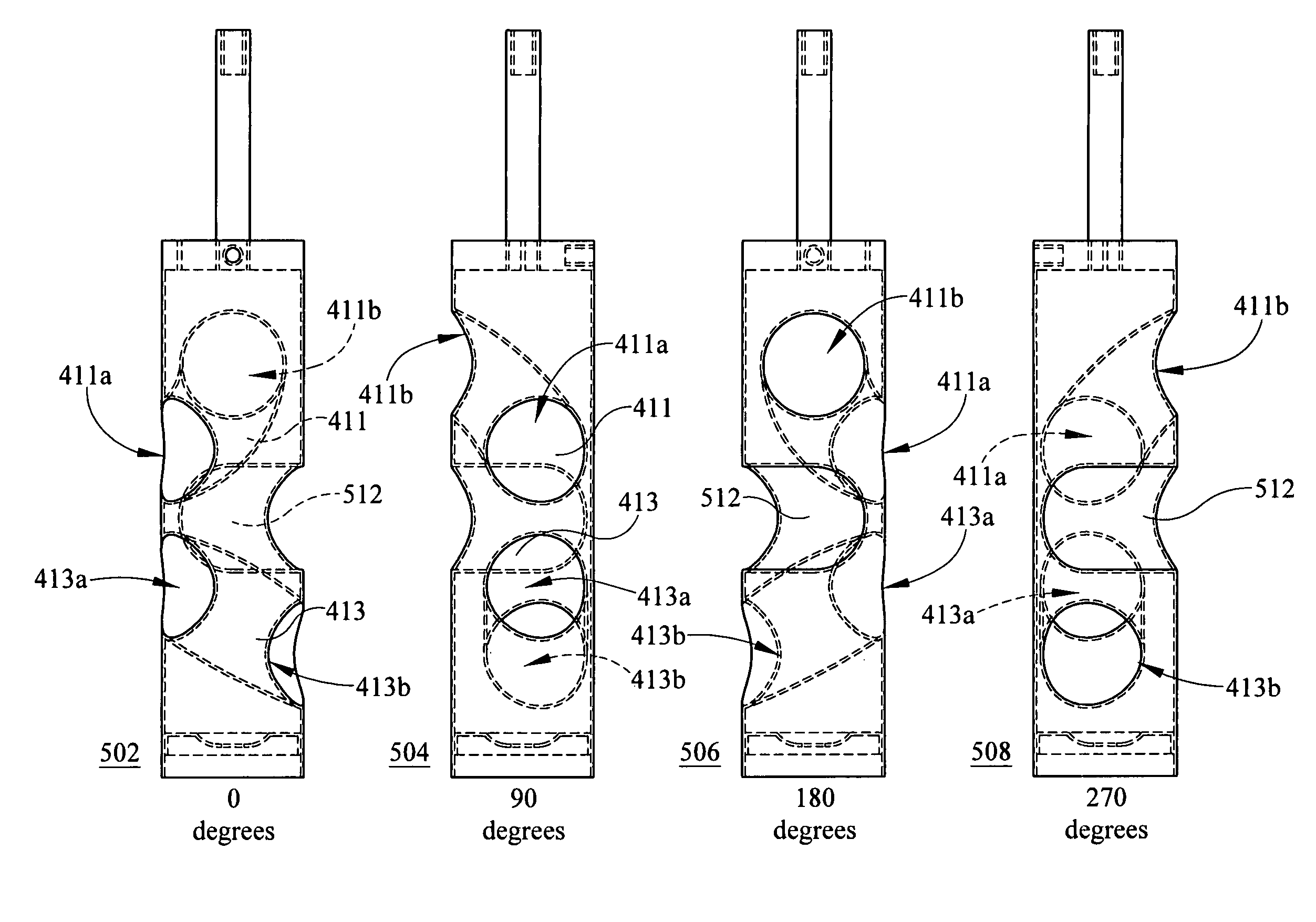
[0035]The Perinet valve is manufactured by determining a final outside diameter and length of piston and piston casing to base the instrument design. Next, six holes are located along the length of hollow, cylindrical tubing that forms the piston body. ...


PUM

PropertyMeasurementUnit
internal diameteraaaaaaaaaa
tensile strengthaaaaaaaaaa

Abstract

The present invention provides a valve assembly designed to regulate air flow through a musical instrument and is designed to avoid bumps typically associated with valve construction that result in distortion and other harmful effects on vibrating columns of air that pass there-through. The valve assembly comprises: a cylindrical-shaped valve casing having openings formed therein that define at least one ingress and at least one egress through which vibrating columns of air pass; and a valve piston received within the valve casing and linearly displaceable therein, the valve piston comprising at least one passageway having a cross-section that is open and u-shaped, whereby other passageways formed in the valve piston are bump-free. The present invention also provides a valve assembly comprising: a cylindrical-shaped valve casing having openings formed therein that define at least one ingress and at least one egress through which vibrating columns of air pass; and a rotary valve received within the valve casing and rotatably displaceable therein. The rotary valve comprises a pair of passageways formed asymmetrically in the body of the rotary valve and at least one of the pair of passageways having a substantially circular cross-section. The rotary valve being further characterized with a land between opening of one of the pair of passageways and the absence of a land for the other of the pair of passageways so as to minimize distortion.

Description

CROSS-REFERENCE TO RELATED PATENTS[0001]This invention is related to and claims benefit of priority to U.S. Provisional Patent Application No. 61 / 210,378 filed Mar. 18, 2009, and entitled Piston Valve For Wind Instrument, the entirety of which is hereby incorporated by reference.FIELD OF THE INVENTION[0002]This invention relates to musical instruments, in particular wind instruments, and, more particularly, to musical instruments having piston valves through which columns of air travel to produce sound.BACKGROUND OF THE INVENTION[0003]Wind instruments are of a variety of types and typically involve a player of the instrument forcing vibrating air columns into an input opening or mouthpiece of the instrument so that the air column travels through the length of the instrument and out the bell or output opening of the instrument. Along the path length altering loops and valves may be placed, such as for trumpets, to alter the length the air column has to travel before exiting the instr...

Claims


Application Information

Patent Timeline
Patent Type & Authority Patents(United States)
IPC IPC(8): G10D7/10
CPCG10D9/04Y10T29/49723Y10T29/49412
Inventor WILK, MARTIN A.
Owner WILK MARTIN A
Why Eureka
Try Eureka