
Apparatus and method for transmitting and receiving data in a communication system using low density parity check code

a communication system and low density parity technology, applied in the field of wireless communication systems, can solve the problems of insufficient use of ldpc codes, inability to minimize the distortion of signals transmitted over a channel, and signal distortion, so as to reduce the distortion of signals in the communication system

Active Publication Date: 2012-07-24
POSTECH ACAD IND FOUND +1
View PDF11 Cites 38 Cited by
  • Summary
  • Abstract
  • Description
  • Claims
  • Application Information

AI Technical Summary

Benefits of technology

This approach reduces Bit Error Rate (BER) and Frame Error Rate (FER), enhancing the overall performance of LDPC codewords by properly distributing higher and lower-degree bits across modulation signal-constituting bits, thereby improving decoding efficiency and reliability in high-order modulation schemes.

Problems solved by technology

However, in communication systems, distortion of signals occurs due to various noises, fading phenomena and Inter-Symbol Interference (ISI) of within and among the different transmission channels.
The LDPC code could not be substantially used since the -technology level in the 1960s was not sufficiently advanced to realize the LDPC code.
Conventionally, however, when the communication system using LDPC codes performs interleaving / deinterleaving, the system uses an arbitrary interleaving / deinterleaving scheme regardless of the LDPC code or reliability characteristics of constituent bits of a high-order modulation signal, or uses an interleaving / deinterleaving scheme where only degrees of variable nodes or check nodes of the LDPC code are considered, thereby failing to minimize distortion of signals transmitted over a channel.
The limitation on recognition prevents maximization of the LDPC code's performance.

Method used


Image

  • Apparatus and method for transmitting and receiving data in a communication system using low density parity check code
  • Apparatus and method for transmitting and receiving data in a communication system using low density parity check code
  • Apparatus and method for transmitting and receiving data in a communication system using low density parity check code

Examples


Embodiment Construction

[0043]Embodiments of the present invention are now described in detail with reference to the accompanying drawings. In the following description, a detailed description of known functions and configurations incorporated herein has been omitted for clarity and conciseness. Terms used herein are defined based on functions in the present invention and may vary according to users, operators' intention or usual practices. Therefore, the definition of the terms should be made based on contents throughout the specification.

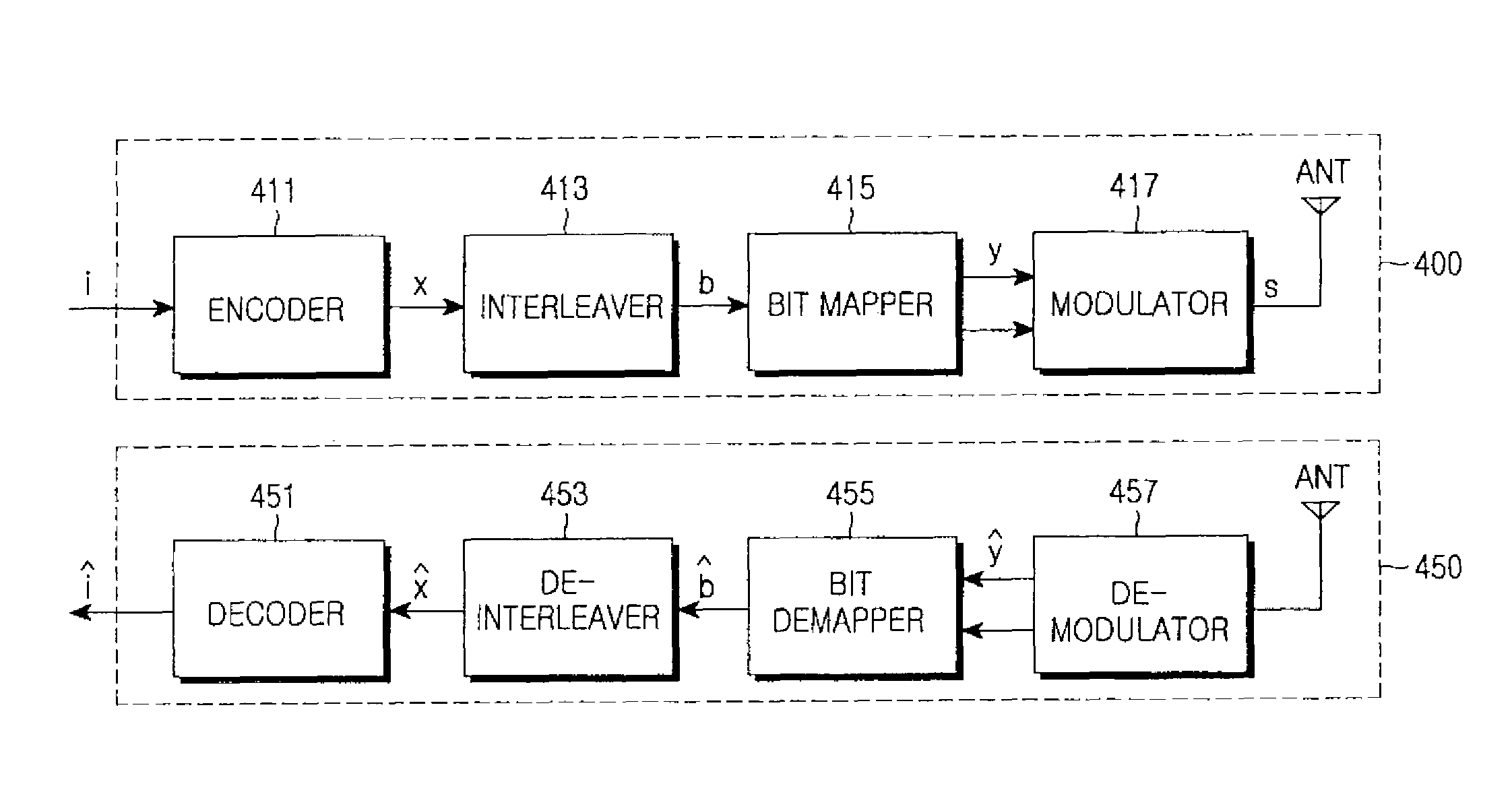
[0044]FIG. 4 is a block diagram illustrating a structure of a communication system using an LDPC code according to an embodiment of the present invention. With reference to FIG. 4, a description will now be made of a structure of a communication system using an LDPC code according to an embodiment of the present invention.

[0045]A transmitter 400 according to the present invention includes an encoder 411, an interleaver 413, a bit mapping into constellation or signal cons...


PUM


Abstract

A method for transmitting data in a communication system using a Low Density Parity Check (LDPC) matrix includes generating an LDPC codeword by encoding information data bits, interleaving the LDPC codeword, mapping the interleaved LDPC codeword to a modulation signal, and generating a mapped signal by mapping the LDPC codeword bits separately to a bit corresponding to a real part and a bit corresponding to an imaginary part of said modulation signal, among bits constituting the modulation signal, generating a modulation signal by high-order-modulating the mapped signal and Radio Frequency (RF)-processing the modulation signal, and transmitting the RF-processed signal via a transmission antenna.

Description

CLAIM OF PRIORITY[0001]This application claims the benefit of the earlier filing date, pursuant to 35 U.S.C. §119(a), to that Korean Patent Application filed in the Korean Intellectual Property Office on Nov. 8, 2007 and assigned Serial No. 2007-113641, the disclosures of which are incorporated herein by reference.BACKGROUND OF THE INVENTION[0002]1. Field of the Invention[0003]The present invention relates wireless communication systems, and in particular, to an apparatus and method for transmitting and receiving data in a communication system using Low Density Parity Check (LDPC) codes.[0004]2. Description of the Related Art[0005]Generally, in communication systems, a data transmission / reception process can be outlined as: data generated in a source of a transmission side is wirelessly transmitted over a channel after undergoing source coding, channel coding, interleaving, and modulation and after receiving the wirelessly transmitted signal at the reception side, the reception side...

Claims


Application Information

Patent Timeline
Patent Type & Authority Patents(United States)
IPC IPC(8): H03M13/00
CPCH03M13/11H03M13/255H03M13/2707H04L27/3488H04L1/007H04L1/0071H04L27/3416H04L1/0057H04L1/00H04L65/00
Inventor JEONG, HONG-SILMYUNG, SEHOYUN, SUNG-RYULLEE, HAK-JUKIM, JAE-YOELDO, YOUNG-UKAHN, SEOK-KIYANG, KYEONG-CHEOLYANG, HYUN-KOO
Owner POSTECH ACAD IND FOUND
Learn More