High pressure high temperature viscometer

a high-temperature, viscometer technology, applied in the direction of material thermal analysis, instruments, measurement devices, etc., can solve the problems of inconvenient handling and manipulation, difficult to remove, etc., to improve usability, reduce mass, and facilitate maintenance.

Active Publication Date: 2012-07-31
CHANDLER INSTR
View PDF18 Cites 15 Cited by
  • Summary
  • Abstract
  • Description
  • Claims
  • Application Information

AI Technical Summary

Benefits of technology

[0009]The sample is contained within in a sample cup located inside the pressure vessel. The sample cup serves to separate the sample fluid from pressurizing fluid and facilitates removal of the sample when the plug assembly is removed.
[0010]The sample cup contains a magnet assembly, e.g., a SmCo magnet assembly, a rotor assembly, a thermowell and related bearings and bushing. A bob assembly is supported by a jewel bearing pivot. The magnet assembly couples to an opposing magnet assembly that is located outside of the pressure vessel, e.g., a second SmCo magnet assembly. By rotating the outer magnet assembly at known speeds using a stepper motor, motion of the inner magnet assembly and rotor is induced. The thermowell provides a means to accurately measure the sample temperature on the centerline of the assembly within the confines of the bob assembly.
[0011]The sample cup is pressure balanced using high pressure ports that connect to internal and external volumes. Therefore, the sample cup does not resist the pressure and may be constructed with a low mass. The external surface of the sample cup is knurled to improve usability and to improve heat transfer.
[0012]The rotor assembly includes external helical flutes that are used to induce circulation of the sample as the rotor assembly is rotated. The circulation path includes the annular volume outside of the rotor assembly, a baffle, an annular volume outside of the bob assembly, ports located in the conical top of the bob assembly, and a volume surrounding the magnet assembly. The baffle above the bob assembly is used to eliminate or reduce the angular momentum of the sample induced by the helical flutes.
[0013]Torque, from which shear stress is calculated, is determined by sensing the angular displacement of a spring, e.g., a linear BeCu spring, attached to the bob assembly confined within the sample cup and pressure vessel. The angular displacement of the spring is measured using a high resolution optical encoder that is magnetically coupled to the spring using a magnet assembly, e.g., made up of SmCo magnets. Through appropriate calibration of the spring, angular displacement is related to torque and shear stress. To enhance the sensitivity of the torque measurement through reduction of frictional effects, the optical codewheel within the encoder assembly is supported by sapphire jewel bearings.
[0016]Since the sample cup is pressure balanced, the sample cup and viscometer components may be constructed of a reduced mass. The pressure vessel remains mounted in the instrument chassis. The sample cup containing the viscometer components and sample is removed as an assembly. This arrangement eliminates a need to transport the pressure vessel and assists in separating the sample from the pressurizing fluid. Therefore, the viscometer of the invention provides improved usability, convenience and ease of maintenance.

Problems solved by technology

To withstand high temperatures and pressures, the pressure vessel is constructed of heavy materials and, is therefore, difficult to remove and inconvenient to handle and manipulate.

Method used


Image

  • High pressure high temperature viscometer
  • High pressure high temperature viscometer
  • High pressure high temperature viscometer

Examples


Embodiment Construction

[0025]Before explaining the present invention in detail, it is important to understand that the invention is not limited in its application to the details of the construction illustrated and the steps described herein. The invention is capable of other embodiments and of being practiced or carried out in a variety of ways. It is to be understood that the phraseology and terminology employed herein is for the purpose of description and not of limitation.

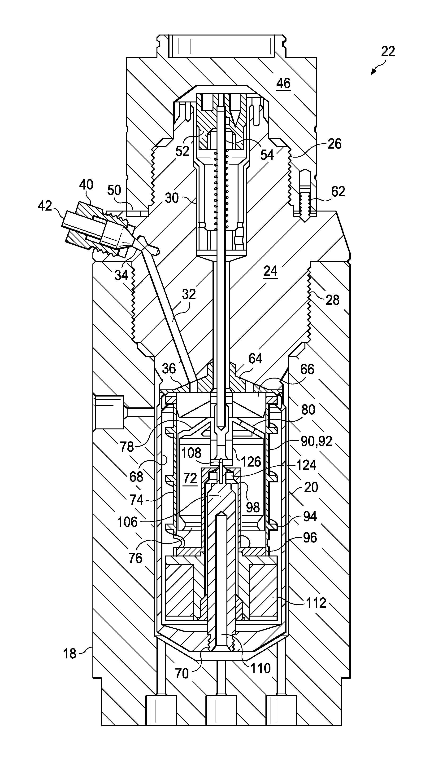
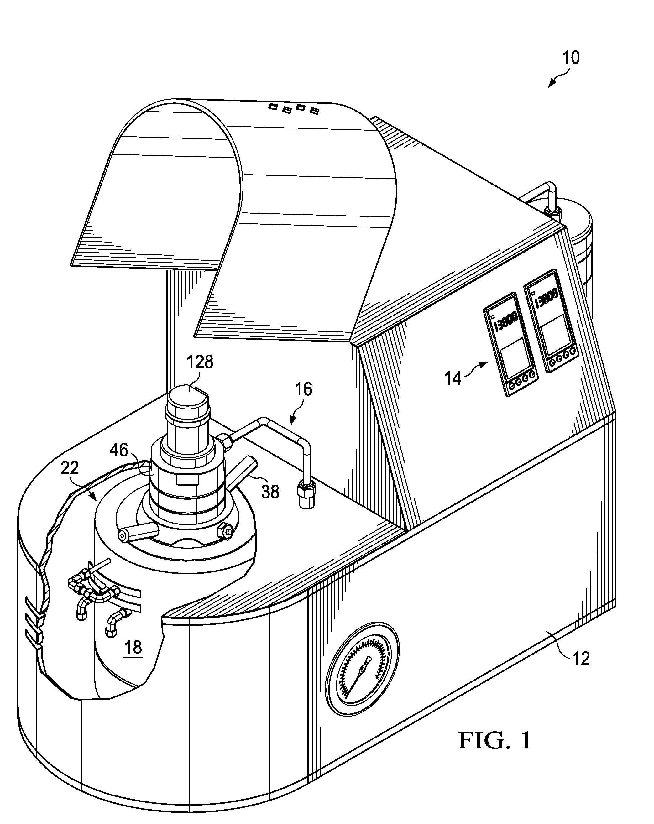
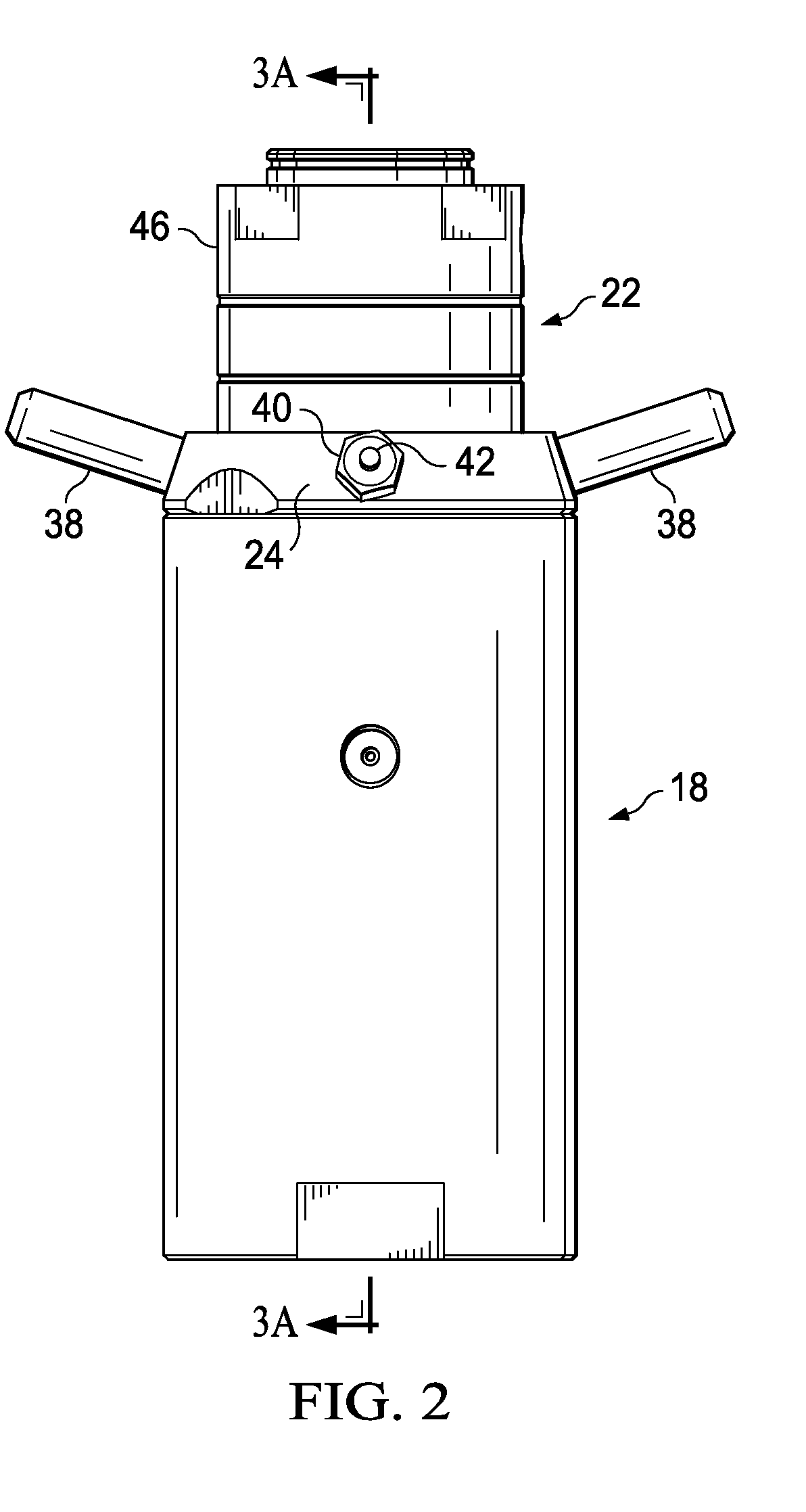
[0026]Referring now to FIGS. 1-7, shown is viscometer unit 10 (FIG. 1) for measuring high temperature and high pressure samples. Viscometer unit 10 includes case enclosed chassis 12. The case houses electronics 14 and hydraulic and pneumatic components 16. Viscometer unit 10 includes a chassis mounted pressure vessel 18 (FIGS. 1-7) that defines receptacle 20 (FIGS. 3A, 3B). Plug assembly 22 is received within receptacle 20 of pressure vessel 18. Plug assembly 22 includes plug top 24 having upper threads 26 and lower threads 28 (FIG. 3...


PUM

PropertyMeasurementUnit
pressuresaaaaaaaaaa
temperaturesaaaaaaaaaa
interior volumeaaaaaaaaaa

Abstract

A couette viscometer used to determine the rheological properties of Newtonian or non-Newtonian solid-laden or non-solid-laden fluids used as completion or treatment fluids in oil and / or gas wells. The instrument is capable of measuring the properties of a heated, e.g., 600° F. / 316° C., and pressurized sample, e.g., 30,000 psig / 207 MPa, at a variety of temperatures, pressures, and shear rates. The pressure vessel is mounted in the chassis of the instrument and the vessel plug containing the viscometer components and sample may be removed as an assembly. This arrangement reduces the mass of the plug assembly, eliminating the need to transport the pressure vessel and assists in separating the sample from the pressurizing fluid. Ultimately, this arrangement improves the usability, convenience and maintenance associated with operating the instrument.

Description

FIELD OF THE INVENTION[0001]The present invention relates generally to a couette viscometer for measuring samples at high pressure and high temperature conditions. More particularly, the viscometer of the invention is designed to improve usability, convenience and maintenance associated with operating the instrument.BACKGROUND OF THE INVENTION[0002]Rotational viscometers measure fluid shear stress created by known shear rates. Viscosity is defined as the ratio of shear stress to shear rate, commonly expressed in units of Poise. The shear stress is proportional to the torque induced on a cylindrical object immersed in a fluid surrounded by a concentric cylindrical surface that is rotated at known speeds. The shear rate is a function of the rotational speed and the geometry.[0003]One type of rotational viscometer is a couette viscometer. In a couette viscometer, liquid whose viscosity is to be measured fills a space between two vertical coaxial cylinders. The inner cylinder is suspend...

Claims


Application Information

Patent Timeline
Patent Type & Authority Patents(United States)
IPC IPC(8): G01N11/14
CPCG01N11/14G01N2011/0006G01N2011/002
Inventor MOON, JOHN JEFFERYAINLEY, BRIAN ROLAND
Owner CHANDLER INSTR
Why Eureka
Try Eureka