Radio-frequency thermal balloon catheter

a radiofrequency and thermal balloon technology, applied in the field of radiofrequency thermal balloon catheters, can solve the problems of unavoidable liquid inside the balloon heated in a non-uniform temperature distribution, and the tissues in contact with the balloon cannot be uniformly heated, so as to reduce the upper-lower temperature difference and ensure the thermal treatment of the lesion

Active Publication Date: 2012-07-31
JAPAN ELECTEL
View PDF25 Cites 121 Cited by
  • Summary
  • Abstract
  • Description
  • Claims
  • Application Information

AI Technical Summary

Benefits of technology

[0006]Accordingly, it is an object of the present invention to solve the foregoing problems in the prior art and to provide a radio-frequency thermal balloon catheter provided with a balloon, and capable of reducing the upper-lower temperature difference due to convection to naught and of uniformly heating tissues in contact with the balloon at an optimum temperature for the safe thermal treatment of a lesion.
[0020]According to the present invention, the radio-frequency thermal balloon catheter is provided with the swirling current producing means for making a fluid contained in the balloon swirl up and down in the balloon so as to reduce the upper-lower temperature difference due to convection of the fluid to naught. Therefore, the radio-frequency thermal balloon catheter is capable of surely reducing the upper-lower temperature difference due to convection of the fluid to naught and of uniformly heating tissues in contact with the balloon d at an optimum temperature for the safe thermal treatment of a lesion.
[0021]When a part of the balloon in contact with tissues is kept at a temperature between 60° C. and 65° C. for a time between 3 and 5 min, a three-dimensional, transmural, necrotic layer can be safely formed without forming thrombi and without causing ulceration due to the vaporization of tissues. Thus origin of arrhythmia can be treated by cauterization. When the isolation of the pulmonary vein ostium and the cauterization of the atrial muscles around the pulmonary vein ostium are performed, the atrial fibrillations that may be otherwise caused by those treated lesion can be permanently healed. Since a circular part of the exit of the right ventricle can be transmuraly cauterized, ventricular tachycardia and ventricular fibrillation that may be otherwise caused by the treated lesion can be permanently healed.
[0022]When tissues affected by arteriosclerosis are heated at temperatures in the range of 43° C. to 45° C. for 20 min or longer, the Apotosis of inflammatory cells, such as labilizing macrophages, occurs and thereby tissues affected by arteriosclerosis can be stabilized.
[0023]The radio-frequency thermal balloon catheter can be applied to the local thermal treatment for cancer. It is known that cancer cells can be controlled and extinguished by heating the same at temperatures in the range of 43° C. to 45° C. for 20 min or longer. The radio-frequency thermal balloon catheter of the present invention can be effectively applied to the treatment for bronchogenic cancer, bile duct cancer, liver cancer and prostate cancer.

Problems solved by technology

In addition, the liquid inside the balloon is heated unavoidably in a non-uniform temperature distribution due to convention.
Hence tissues in contact with the balloon cannot be uniformly heated.

Method used


Image

  • Radio-frequency thermal balloon catheter
  • Radio-frequency thermal balloon catheter
  • Radio-frequency thermal balloon catheter

Examples


second embodiment

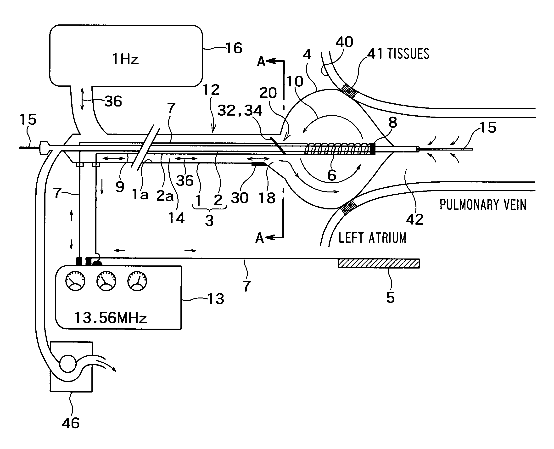
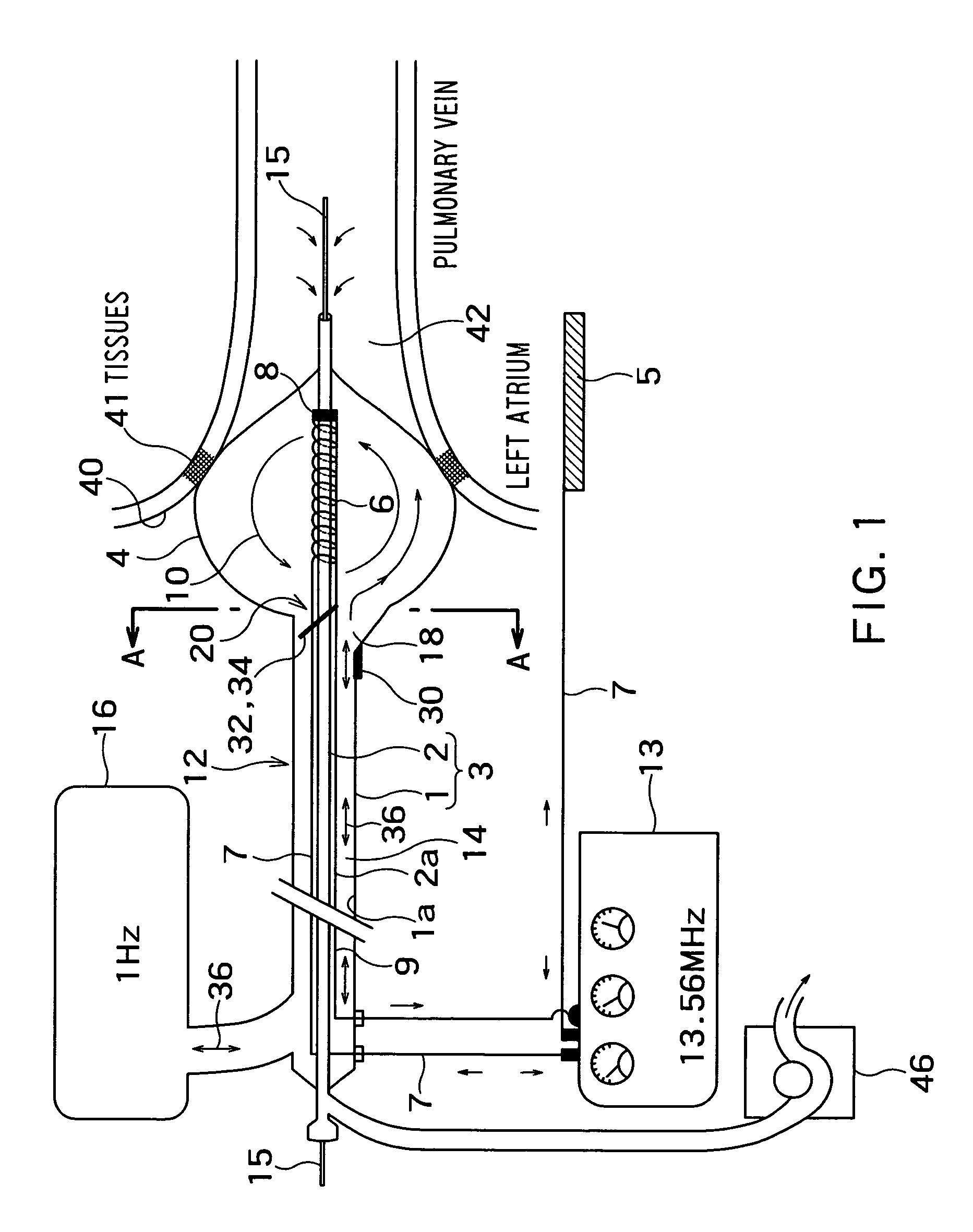
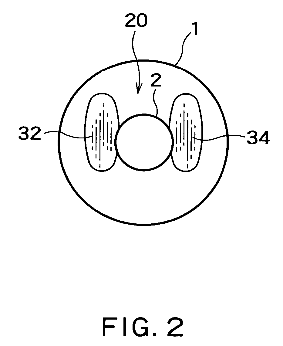
[0060]In the radio-frequency thermal balloon catheter in the second embodiment, a vibration propagating direction deflecting device 20 includes a pipe 50 disposed near the inlet 18 of a balloon 4. The pipe has an open end 51 and a closed end. A first hole 52 and a second hole 53 are formed in the same side of the pipe 50. An inner tube 2 penetrates the pipe 50 closely. The first hole 52 and the second hole 53 are on the opposite sides, respectively, of the inner tube 2. As shown in FIG. 4, the pipe 50 is held on a holding plate 55 fitted in an outer tube 1 and joined to the inside surface of the outer tube 1. Since the interior of the outer tube 1 is partitioned by the holding plate 55, a vibration propagating passage 14 communicates with the interior of the balloon 4 by means of the open end 51, the first hole 52 and the second hole 53 of the pipe 50. The pipe 50 is inclined as shown in FIG. 3 to deflect the direction of propagation of a vibration propagated through the vibration p...

fourth embodiment

[0067]A vibration propagating direction deflecting device 20 includes an extension tube 70 having a closed tip and provided with an opening 71 in its lower side. A pair of radio-frequency electrodes 6a ad 6b are wound round the extension tube 70. This radio-frequency thermal balloon catheter in the fourth embodiment does not use any counter electrode to be attached to the surface of the subject's body. The radio-frequency electrodes 6a and 6b are connected to a radio-frequency generator 13 respectively by lead wires 7a and 7b.

[0068]The radio-frequency thermal balloon catheter is turned so as to place an radiopaque mark 30 at a predetermined position so that the opening 71 opens downward to deflect the direction of propagation of a vibration propagated through a vibration propagating passage 14 downward in the balloon 4. The vibration propagated downward in the balloon 4 produces whirling currents 10 in the balloon 4. The vibration is propagated from the balloon 4 through the openin...


PUM


Abstract

A radio-frequency thermal balloon catheter includes a catheter tube including an outer tube and an inner tube, a balloon connected to an end part of the outer tube and an end part of the inner tube, and capable of coming into contact with a target diseased part when inflated, a radio-frequency electrode placed in the wall of the balloon or inside the balloon to transmit radio-frequency current, a lead wire electrically connected to the radio-frequency electrode, a temperature sensor capable of measuring temperature inside the balloon, and a swirling current producing means for making a fluid contained in the balloon swirl in a vertical plane in the balloon so as to reduce an upper-lower temperature difference between an upper part and a lower part of the interior of the balloon due to convection of the fluid to naught.

Description

TECHNICAL FIELD[0001]The present invention relates to a radio-frequency thermal balloon catheter and, more specifically, to a balloon catheter for the radio-frequency thermal treatment for cardiovascular diseases.BACKGROUND ART[0002]Medial treatments for diseases, such as origin of arrhythmia and arteriosclerosis, have been proposed in, for example, Jpn. Pat. Nos. 2538375, 2510428 and 2574119, U.S. Pat. No. 6,491,710 B2 and JP 2003-120850 A (JP '850). Those known medical treatments use an inflatable balloon internally provided with a radio-frequency electrode. A radio-frequency electric field is created around the radio-frequency electrode to heat tissues in contact with the balloon for treatment.[0003]Tissues in contact with a balloon need to be heated as uniformly as possible to treat the tissues satisfactorily. A radio-frequency electrode having a three-dimensional shape cannot be disposed in perfect alignment with the balloon inside the balloon and hence the liquid contained in ...

Claims


Application Information

Patent Timeline
Patent Type & Authority Patents(United States)
IPC IPC(8): A61B18/12A61B18/00A61B18/14A61F2/958A61M25/00
CPCA61B18/04A61B18/1492A61B2018/00023A61B2018/00214A61B2018/0022A61B2018/00375A61B2018/046A61M25/0026A61M25/1006
Inventor SATAKE, SHUTARO
Owner JAPAN ELECTEL
Why Eureka
Try Eureka