
Utility managed virtual power plant utilizing aggregated thermal energy storage

a technology of thermal energy storage and managed virtual power plants, which is applied in the direction of electric controllers, domestic cooling devices, instruments, etc., can solve the problems of limited success of energy storage systems of current air conditioning units and difficulty in achieving high-efficiency

Active Publication Date: 2012-08-07
BLUE FRONTIER LLC
View PDF76 Cites 66 Cited by
  • Summary
  • Abstract
  • Description
  • Claims
  • Application Information

AI Technical Summary

Benefits of technology

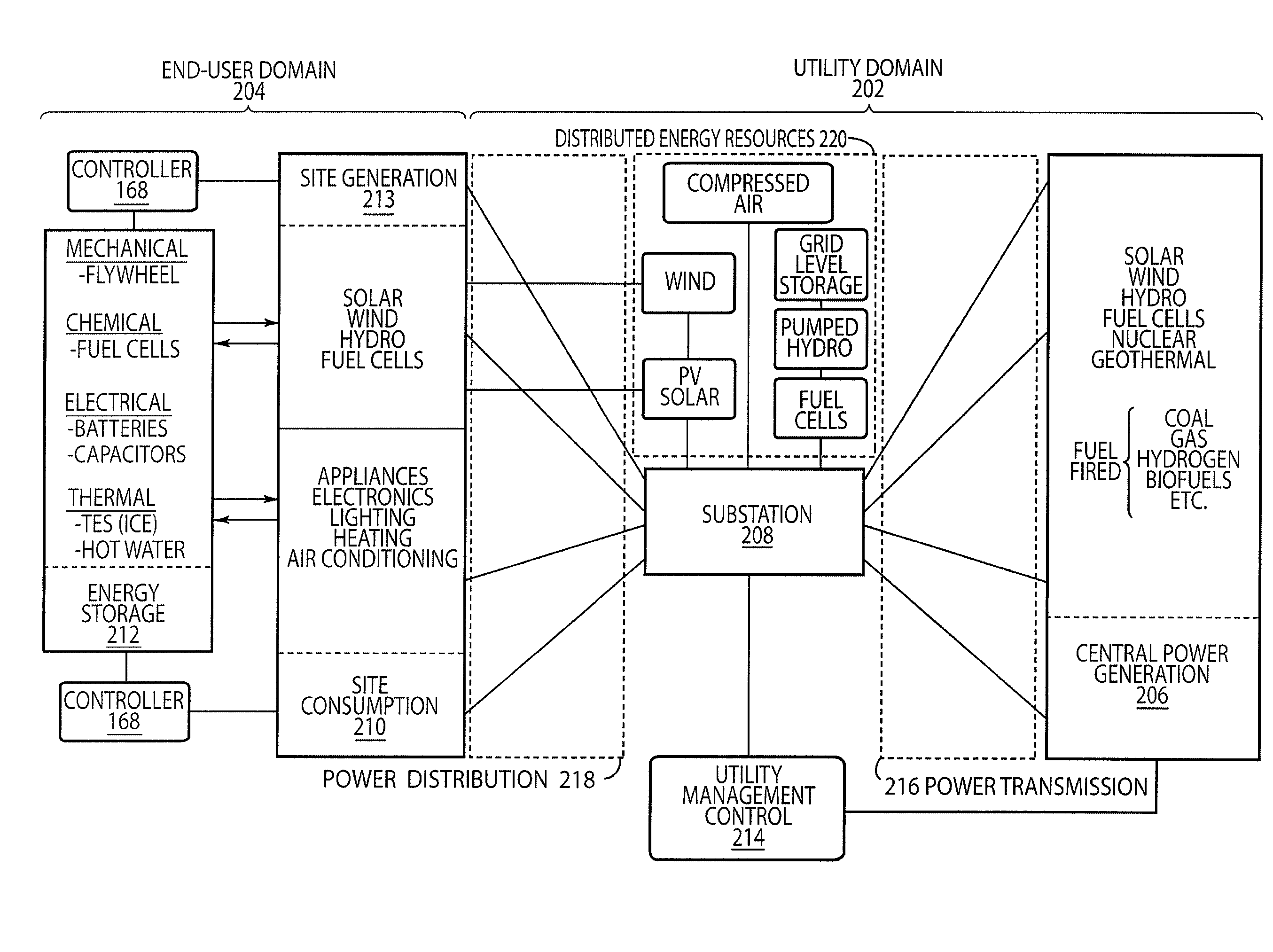
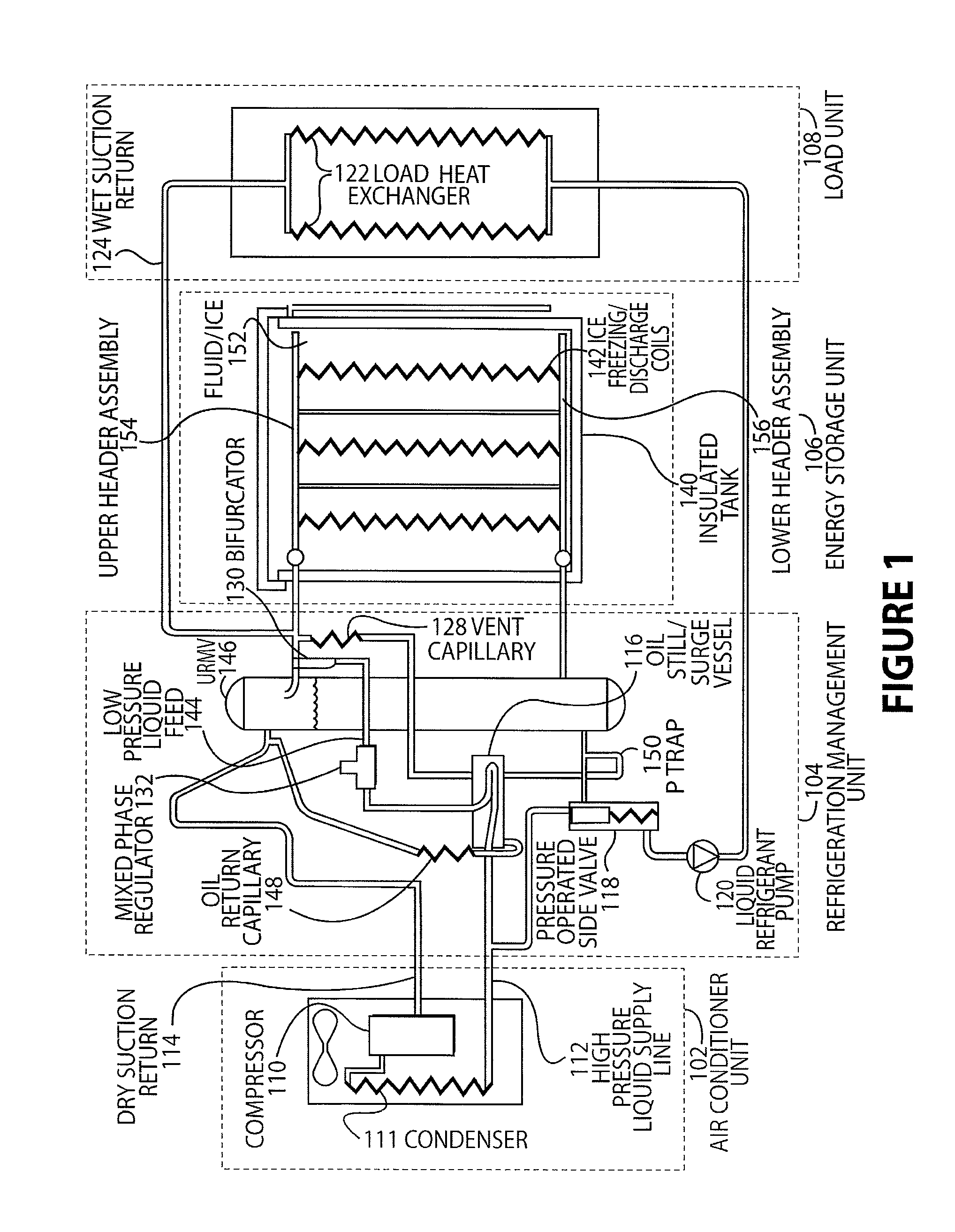
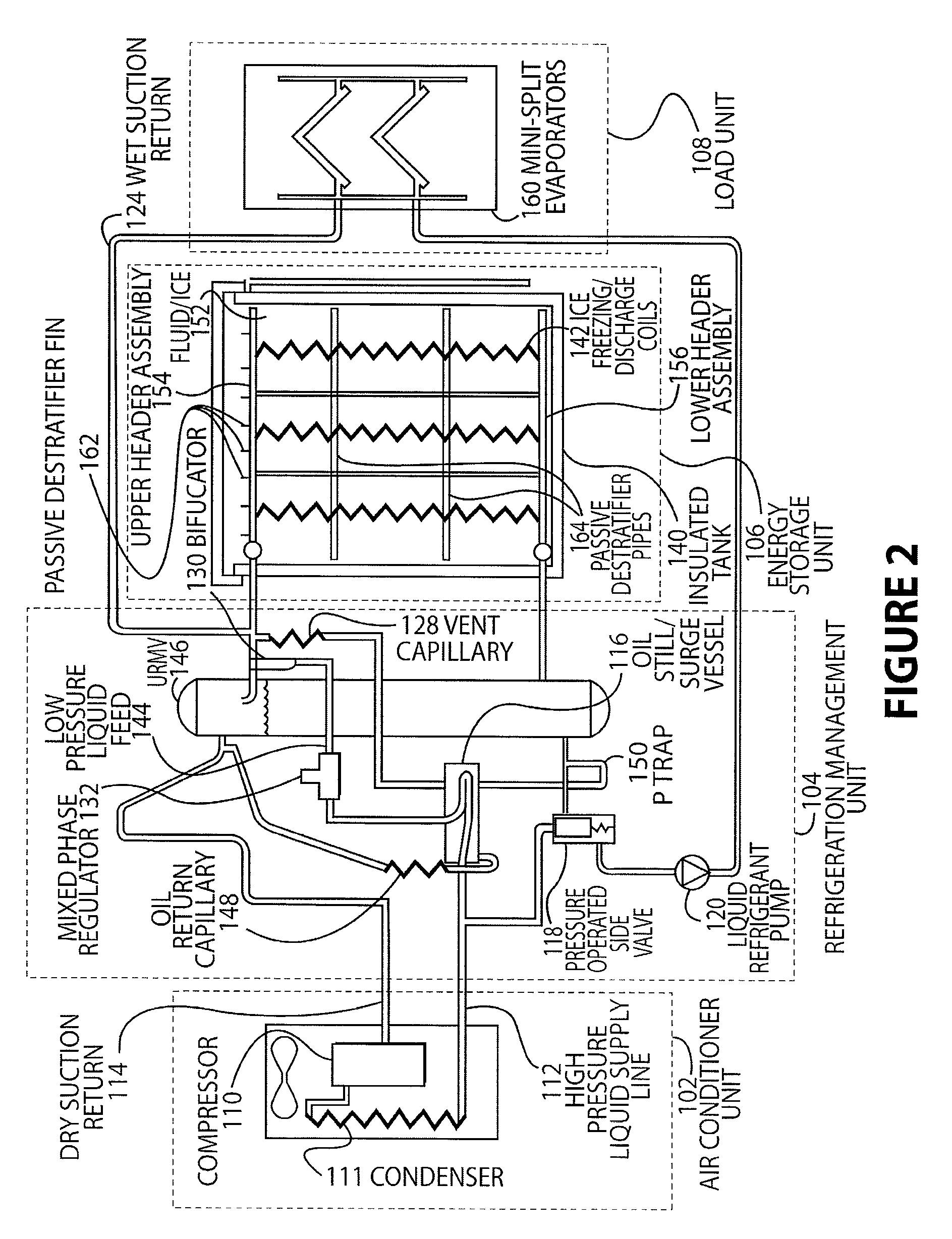
"The present invention relates to a system and method for temporarily shifting the demand for electrical power and cooling supplied to an end-user by an electrical utility. The system includes an energy storage unit that receives and converts alternating current electrical energy from the utility, and stores it for later use. A controller manages the operation of the energy storage unit and supplies the stored energy to the end-user. A communications link connects the utility manager to the controller, allowing the utility to manage and control the operation of the controller. The system can also include a thermal energy storage unit that converts electric energy to thermal energy, stores it, and supplies it to the end-user to reduce their demand for electric energy. The method involves receiving and converting alternating current electrical energy, storing it, and controlling the amount and time period of the energy supplied to the end-user. The technical effects of the invention include reducing peak demand, improving efficiency, and providing flexibility for the electrical utility and end-user."

Problems solved by technology

Current air conditioning units having energy storage systems have had limited success due to several deficiencies including reliance on water chillers that are practical only in large commercial buildings, and have difficulty achieving high-efficiency.

Method used


Image

  • Utility managed virtual power plant utilizing aggregated thermal energy storage
  • Utility managed virtual power plant utilizing aggregated thermal energy storage
  • Utility managed virtual power plant utilizing aggregated thermal energy storage

Examples


Embodiment Construction

[0020]While this invention is susceptible to embodiments in many different forms, there is shown in the drawings and will be described herein, in detail, specific embodiments thereof with the understanding that the present disclosure is to be considered as an exemplification of the principles of the invention and is not to be limited to the specific embodiments described.

[0021]The disclosed embodiments offer the advantage of using power from electric utility companies during low demand, off-peak hours, which are usually at night, when these companies use their most efficient equipment. For example, high efficiency electric generators, typically stream-driven, produce a kilowatt-hour (KWH) for approximately 8,900 BTU. In contrast, a peak hour high capacity electrical generator, such as a gas turbine, can use as much as 14,000 BTU to produce the same KWH of electricity. Second, the transmission lines also run cooler at night resulting in higher efficiency of energy usage. Finally, for...


PUM


Abstract

Disclosed is a system and method for providing power generation and distribution with on-site energy storage and power input controlled by a utility or a third party manager. The system allows a utility manager to decide and direct how energy is delivered to a customer on both sides of the power meter, while the customer directs and controls when and how much energy is needed. In the disclosed embodiments, the utility controls the supply (either transmitted or stored) and makes power decisions on a system that acts as a virtual power plant, while the end-user retains control of the on-site aggregated power consumption assets. The disclosed systems act to broker the needs of the utility and end-user by creating, managing and controlling the interface between these two entities.

Description

CROSS REFERENCE TO RELATED APPLICATIONS[0001]This application is a continuation-in-part of U.S. patent application Ser. No. 11 / 610,982 entitled “Refrigeration Apparatus” by Ramachandran Narayanamurthy et al., filed Dec. 14, 2006, which is a continuation-in-part of U.S. patent application Ser. No. 10 / 967,114 entitled “Refrigeration Apparatus” by Ramachandran Narayanamurthy et al., filed Oct. 15, 2004, which claims the benefit of and priority to U.S. provisional application No. 60 / 511,952, entitled “Refrigerant Based High Efficiency Energy Storage and Cooling System”, filed Oct. 15, 2003. The entire contents of the above listed applications are hereby specifically incorporated herein by reference for all they disclose and teach.BACKGROUND OF THE INVENTION[0002]With the increasing demands on peak power consumption, ice storage is an environmentally benign method that has been utilized to shift air conditioning power loads to off-peak times and rates. A need exists not only for load shi...

Claims


Application Information

Patent Timeline
Patent Type & Authority Patents(United States)
IPC IPC(8): F25D3/00
CPCF24F5/0017G05B15/02F25D16/00F25B2400/16Y02E60/147F25B2400/24Y02E60/14G05B11/01
Inventor PARSONNET, BRIANNARAYANAMURTHY, RAMACHANDRAN
Owner BLUE FRONTIER LLC
Learn More