Photo acoustic detector with improved signal processing

a technology of signal processing and detector, applied in the field of photo acoustic detector, can solve the problem that the integrating current of the detector over a whole period does not provide information about the concentration of the sample in the sample mixture, and achieve the effect of shortening the time needed for taking a sample, fast detection, and the same tim

Inactive Publication Date: 2012-08-07
KONINK PHILIPS ELECTRONICS NV
View PDF9 Cites 1 Cited by
  • Summary
  • Abstract
  • Description
  • Claims
  • Application Information

AI Technical Summary

Benefits of technology

[0008]The detector element provides a detector current that oscillates at the resonance frequency of the pressure variations induced by the light source in the sample mixture. The operating of the hold switch in the integrating amplifier results in sampling only a predetermined interval during a period of the detector current. The fixed interval is chosen shorter than the whole period, because the positive part of the oscillating detector current compensates the negative part and, as a consequence, the integrated value of the detector current over a whole period does not depend on the amplitude of the pressure variations. Integrating the detector current over a whole period does not provide information about the concentration of the sample in the sample mixture. By only integrating a shorter predetermined interval of the signal, this compensation does not occur and a higher amplitude results in a higher integrated value. Each obtained signal sample is a measure of the concentration of the sample. By adding the obtained signal samples for multiple periods of the detector current, the gain of the output signal is improved and lower sample concentration can be detected.
[0010]Preferably the detector current and the hold signal, SWHOLD, are in phase or in antiphase. By sampling 50% of each period of the detector current, only the positive part of the detector current or only the negative part of the detector current is integrated. By adding only the positive parts of multiple periods of the signal from the oscillator element, the gain and the signal to noise ratio of the detector is much improved, thereby resulting in a more sensitive photo acoustic detector. When the detector current and the hold signal SWHOLD are not exactly in phase or in antiphase, the gain of the detector decreases.
[0015]This embodiment also eliminates disadvantages of the above described embodiment wherein the hold signal, SWHOLD, has a frequency equal to the frequency of the detector current and a duty cycle of 50%. That embodiment, if combined with the use of an oscillator element for detection of the pressure variations, shows the disadvantage that the hold switch switches at the same frequency as the resonance frequency of the detector signal. When the hold switch (typically a FET) switches, some small current flows through this switch at the resonance frequency of the oscillator element. As a result the oscillator gets excited a bit, causing an offset in the output signal. So even without laser light and sample molecules, an offset at the output occurs. When switching the hold signal, SWHOLD, at a frequency equal to one third of the frequency of the detector current the hold switch is not operated at the resonance frequency of the oscillator element and the oscillator element does not resonate anymore on switching SWHOLD. As a result, the switching does not influence the detector current.
[0017]This embodiment has the additional advantage, that the time needed for taking a sample is shorter than in the previous embodiment. This results in faster detection with the same signal to noise ratio, or equally fast detection with a better signal to noise ratio. In another embodiment, the processing section is arranged for taking a first and a second measurement by respectively generating a first and a second output signal, the hold signal, SWHOLD, used for the second measurement being phase shifted over half a period of the detector current, and calculating an average output signal from the absolute values of the first and the second output signal.
[0023]For small detector currents, more gain is needed to obtain sufficient signal to noise ratio, which results in a longer integration time. For large detector currents however, less gain is needed, which results in a shorter integration time. By adaptively calculating the total sampling time, the signal to noise ratio can be kept sufficient and the integration time can be kept as short as possible.

Problems solved by technology

Integrating the detector current over a whole period does not provide information about the concentration of the sample in the sample mixture.

Method used


Image

  • Photo acoustic detector with improved signal processing
  • Photo acoustic detector with improved signal processing
  • Photo acoustic detector with improved signal processing

Examples


Embodiment Construction

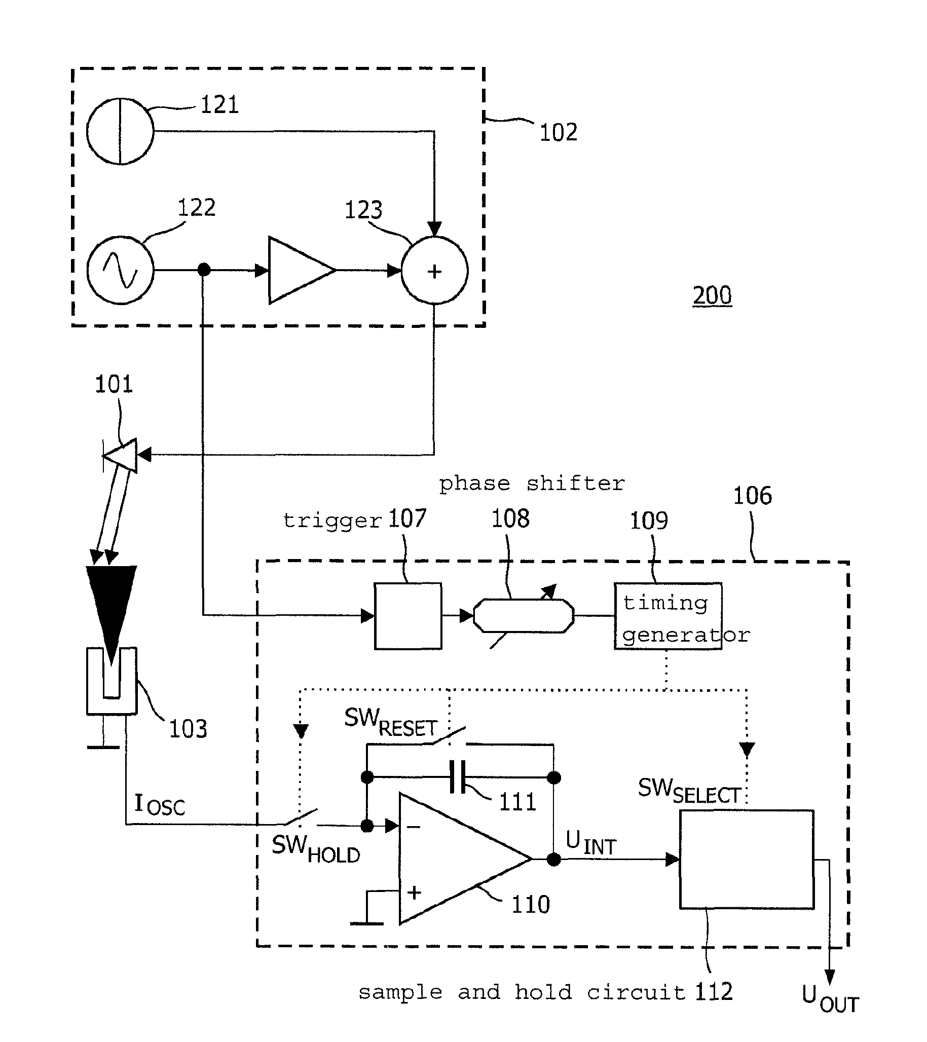
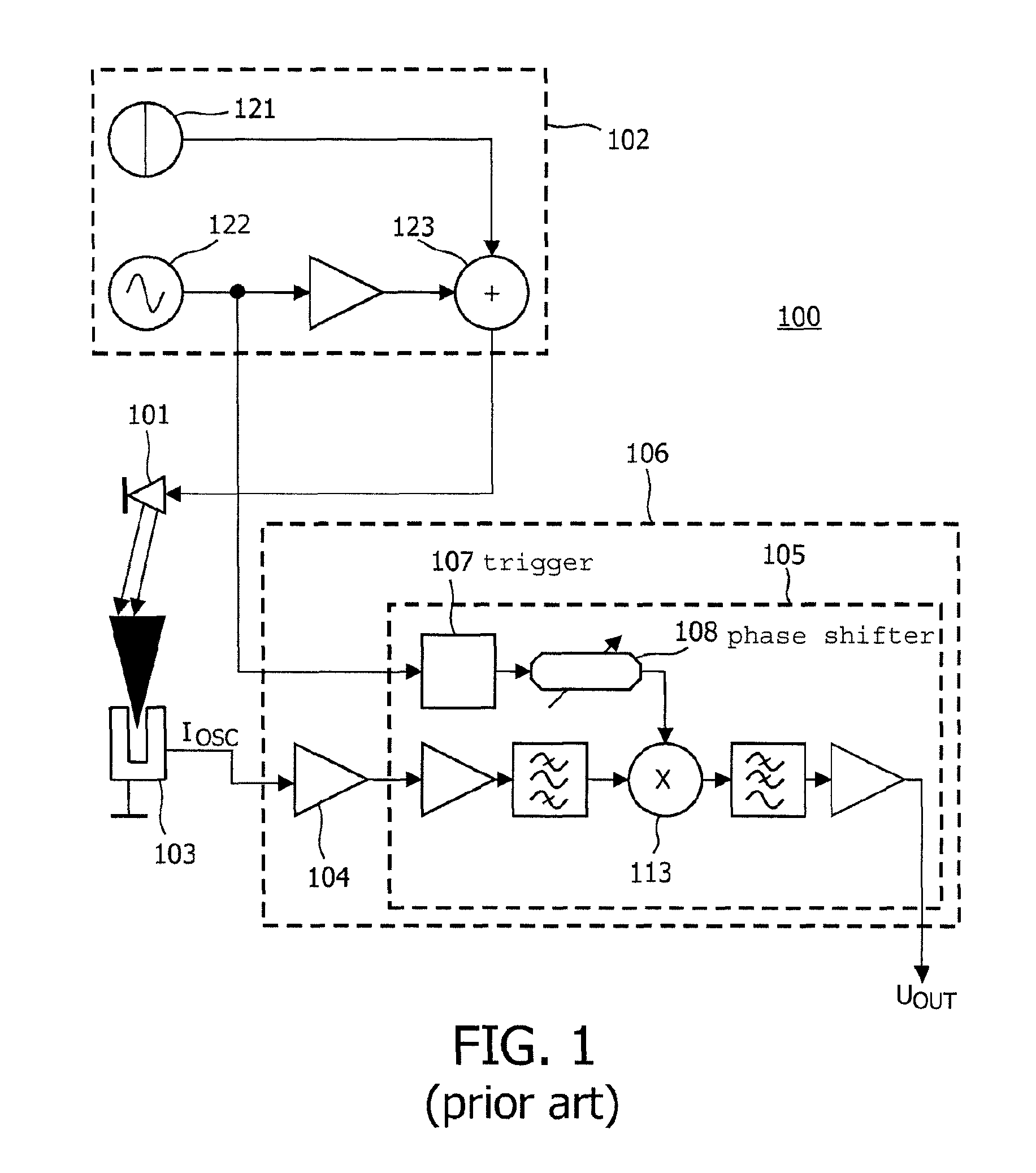
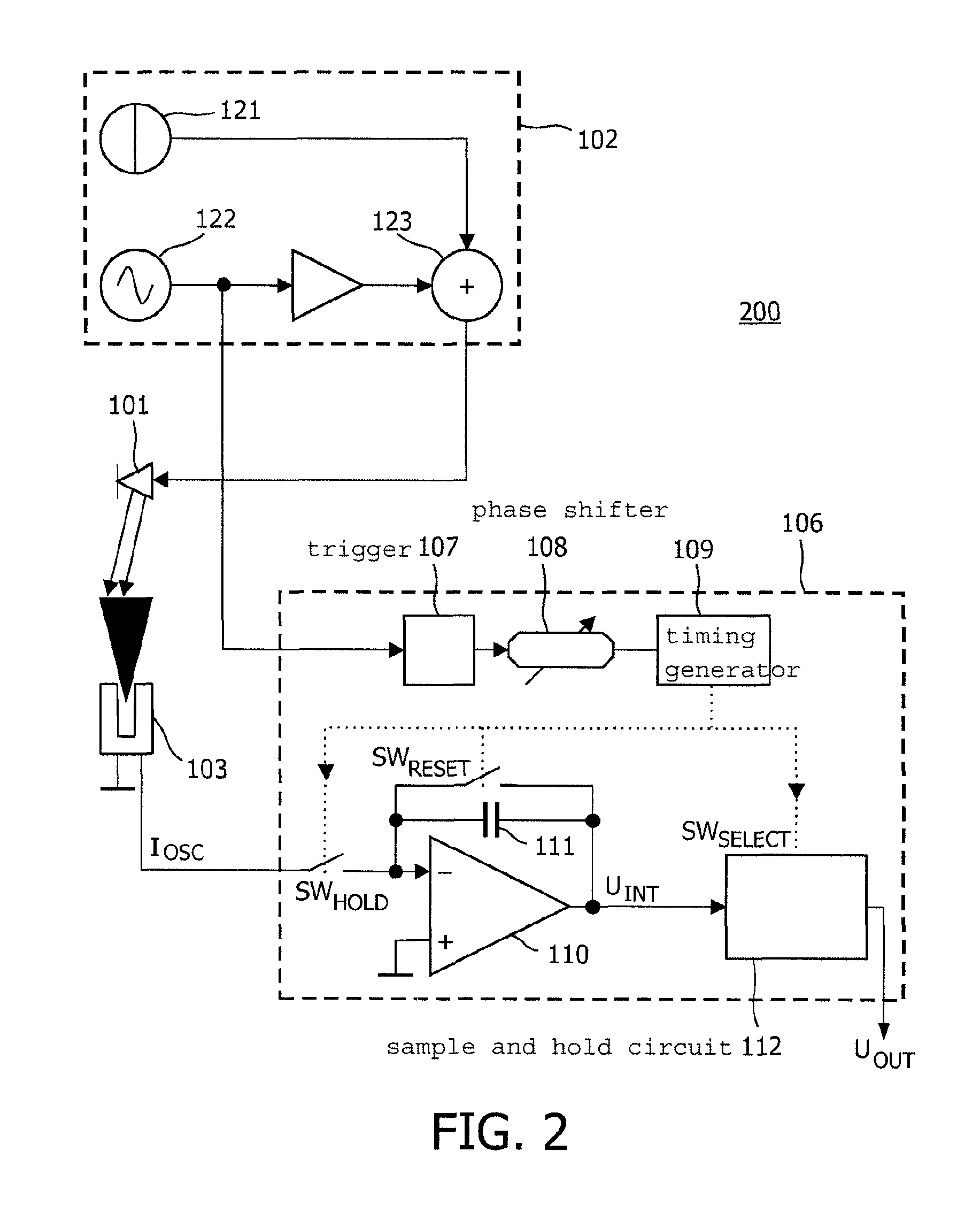
[0033]FIG. 1 schematically shows a prior art photo acoustic detector. The photo acoustic trace gas detector described hereinafter detects trace gas concentrations in gas mixture, but the invention may also be applied to detect tissue, fluid or solid samples in other sample mixtures. The trace gas detector 100 uses a laser diode 101 as a light source. The wavelength of the laser light is chosen such that it can excite the trace gas molecules. Alternatively, other types of laser sources or other light sources, capable of producing a light beam with sufficient energy to excite the trace gas molecules may be used. A laser driver 102 provides a driving signal for the laser diode 101. In this embodiment, the laser driver 102 also functions as a modulator for modulating the light beam. The laser driver 102 comprises a DC source 121 for providing a DC signal and an AC source 122 for providing an AC signal. The DC signal and the AC signal are combined in adder 123 and then provided to the la...


PUM

PropertyMeasurementUnit
concentrationaaaaaaaaaa
pressureaaaaaaaaaa
currentaaaaaaaaaa

Abstract

A photo acoustic detector for detecting a concentration of a sample in a mixture includes a light source for producing a light beam for exciting molecules of the sample, and a light modulator for modulating the light beam for generating pressure variations in the sample mixture, where an amplitude of the pressure variations is a measure of the concentration. The detector further includes a detector element for converting the pressure variations into a detector current and a processing section for processing the detector current to generate an output signal representing the concentration. The processing section includes an integrating amplifier for integrating the detector current, the integrating amplifier being coupled to the detector element via a hold switch, and a timing circuit for generating a hold signal, SWHOLD, for operating the hold switch to couple the integrating amplifier to the detector element during a predetermined interval of the detector current.

Description

CROSS REFERENCE TO RELATED APPLICATION[0001]This application claims the benefit of EP provisional application s / n 06123851.5, filed Nov. 10, 2006, which is incorporated herein by reference. A related application is PCT IB2007 / 054472, “Oscillator Element for Photo Acoustic Detector,” filed Nov. 5, 2007, published as WO 2008 / 056312.TECHNICAL FIELD OF THE INVENTION[0002]The invention relates to a photo acoustic detector for detecting a concentration of a sample in a sample mixture, the photo acoustic detector comprising a light source for producing a light beam for exciting molecules of the sample, a light modulator for modulating the light beam for generating pressure variations in the sample mixture, an amplitude of the pressure variations being a measure of the concentration, a detector element for converting the pressure variations into a detector current, and a processing section for processing the detector current to generate an output signal representing the concentration.BACKGR...

Claims


Application Information

Patent Timeline
Patent Type & Authority Patents(United States)
IPC IPC(8): G01N21/00
CPCG01N21/1702G01N29/022G01N29/2425G01N2021/1708G01N2291/02809G01N2291/02872G01N2291/0427
Inventor HELWEGEN, IVON FRANCISCUSVAN KESTEREN, HANS WILLEM
Owner KONINK PHILIPS ELECTRONICS NV
Why Eureka
Try Eureka