Wind turbine blade shear web connection assembly

a technology of wind turbine blades and shear webs, which is applied in the field of wind turbine blade shear web configuration, can solve the problems of significant rework, difficult to achieve the dimensions of adequate bonding, and inability to accommodate relatively large length variances, and achieve the effect of reducing the overall amount and weight of bonding pas

Active Publication Date: 2012-08-07
GENERAL ELECTRIC CO
View PDF38 Cites 13 Cited by
  • Summary
  • Abstract
  • Description
  • Claims
  • Application Information

AI Technical Summary

Benefits of technology

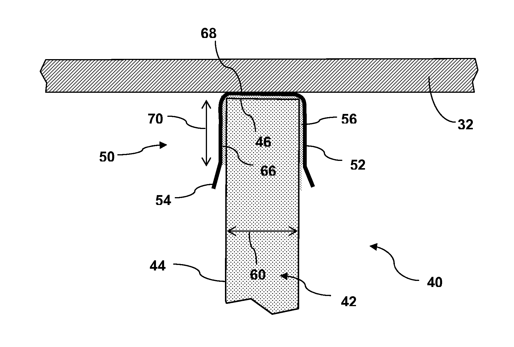
[0008]Another benefit of the channel structure configuration is that the excess bond paste that typically “squeezes out” during the bonding procedure is now more controlled. A large concern arises when the bond paste is allowed to squeeze out freely, whereby it forms an irregular shape that acts as a stress concentration. By controlling the shape of the bond paste with the channel configuration, the stress concentration factor is effectively reduced.
[0012]The transverse end of the shear web may be variously received within the channel structure. In one embodiment, the transverse end may be spaced from the spar cap (or end wall of the channel structure). The space between the transverse end of the shear web and the spar cap may be free of bond material so as to decrease the overall amount and weight of the bond paste. In other embodiments, it may be desired to bond the transverse end of the shear web to the spar cap (or end wall of the channel structure) by essentially encasing the transverse end of the shear web with bond paste within the channel structure.

Problems solved by technology

Achieving these dimensions, as well as an adequate bond, can be difficult and the juncture between the spar caps and shear web is a time-consuming and tedious process that often requires significant re-work.
This configuration, however, does not accommodate relatively large length variances (e.g., shortages) in the shear web and often results in the use of excess bond paste to make up for a length deviation and to achieve the bond width.
The excess paste contributes unnecessary weight to the blade and can break off and result in blade “rattling” during operation of the wind turbine (a not uncommon complaint from wind turbine owners / operators).
Also, air voids and unpredictable squeeze-out of the bond paste in the typical construction can result in areas of decreased bond strength, which is particularly problematic in sections of the blade where repair is not possible from within the blade.

Method used


Image

  • Wind turbine blade shear web connection assembly
  • Wind turbine blade shear web connection assembly
  • Wind turbine blade shear web connection assembly

Examples


Embodiment Construction

[0022]Reference now will be made in detail to embodiments of the invention, one or more examples of which are illustrated in the drawings. Each example is provided by way of explanation of the invention, not limitation of the invention. In fact, it will be apparent to those skilled in the art that various modifications and variations can be made in the present invention without departing from the scope or spirit of the invention. For instance, features illustrated or described as part of one embodiment can be used with another embodiment to yield a still further embodiment. Thus, it is intended that the present invention include such modifications and variations as come within the scope of the appended claims and their equivalents.

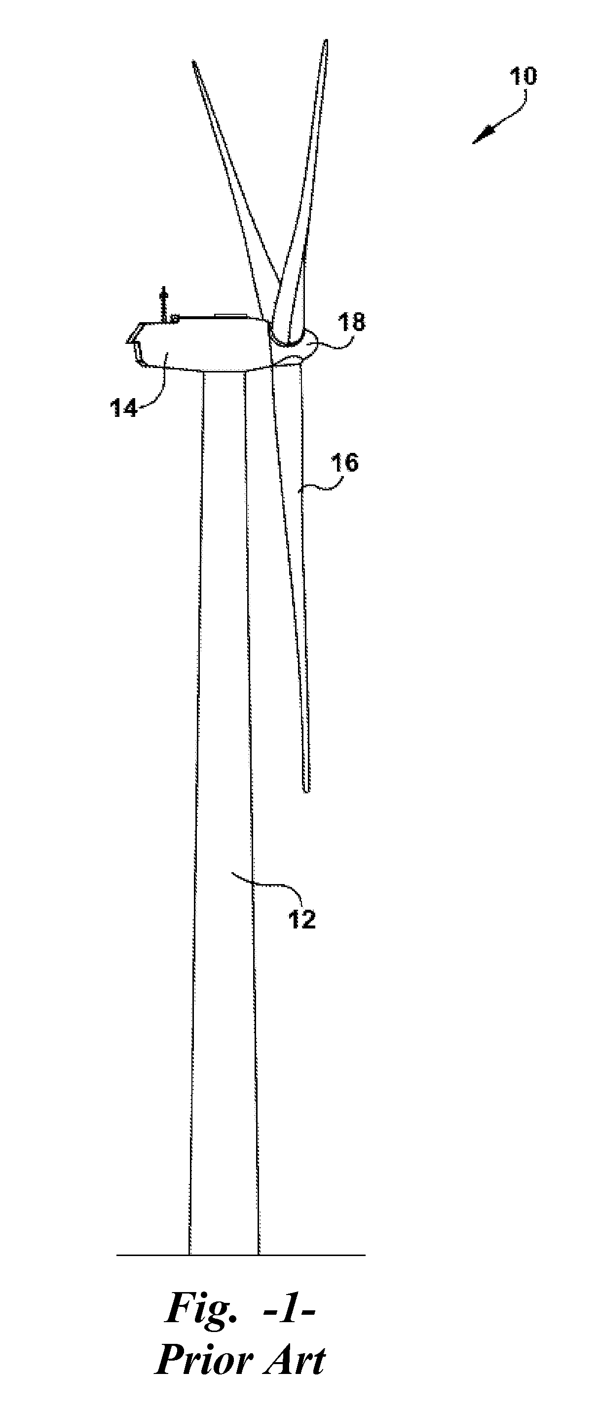
[0023]FIG. 1 illustrates a wind turbine 10 of conventional construction. The wind turbine 10 includes a tower 12 with a nacelle 14 mounted thereon. A plurality of turbine blades 16 are mounted to a rotor hub 18, which is in turn connected to a main flange ...


PUM

PropertyMeasurementUnit
longitudinal lengthaaaaaaaaaa
widthaaaaaaaaaa
lengthaaaaaaaaaa

Abstract

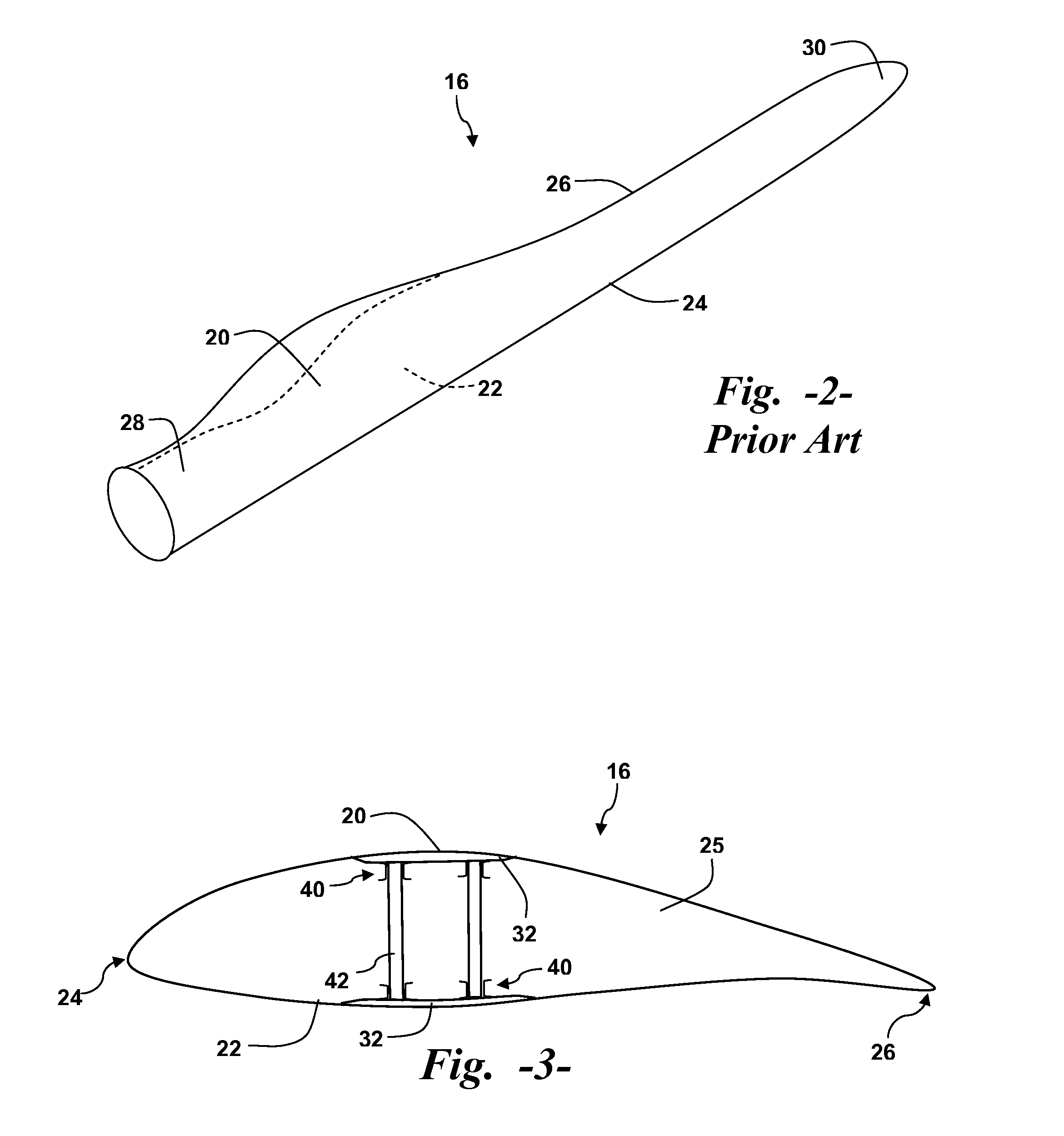
A wind turbine blade has upper and lower shell members with a respective spar cap configured on an internal face of the shell members. A shear web extends between the spar caps along a longitudinal length of the blade. A connection assembly is configured between the transverse ends of the shear web and the spar caps and includes a channel structure configured on the spar cap. The channel structure includes rigid side walls that extend from the spar cap along the longitudinal sides of the shear web. Bond paste is disposed between the channel structure side walls and the longitudinal sides of the shear web.

Description

FIELD OF THE INVENTION[0001]The present invention relates generally to the field of wind turbines, and more particularly to the shear web configuration within the wind turbine blades.BACKGROUND OF THE INVENTION[0002]Turbine blades are the primary elements of wind turbines for converting wind energy into electrical energy. The blades have the cross-sectional profile of an airfoil such that, during operation, air flows over the blade producing a pressure difference between the sides. Consequently, a lift force, which is directed from a pressure side towards a suction side, acts on the blade. The lift force generates torque on the main rotor shaft, which is geared to a generator for producing electricity.[0003]The turbine blades typically consist of a suction side shell and a pressure side shell that are bonded together at bond lines along the trailing and leading edges of the blade. An internal shear web extends between the pressure and suction side shell members and is bonded to spar...

Claims


Application Information

Patent Timeline
Patent Type & Authority Patents(United States)
IPC IPC(8): F03D11/00
CPCF03D1/065F03D1/0683B29C65/52B29C66/112B29C66/114B29C66/324B29C66/636B29C66/721B29L2031/085Y02E10/721B29C65/48B29C66/5326B29C66/54B29C66/43441Y02E10/72Y02P70/50F03D1/0675
Inventor YARBROUGH, AARON
Owner GENERAL ELECTRIC CO
Why Eureka
Try Eureka